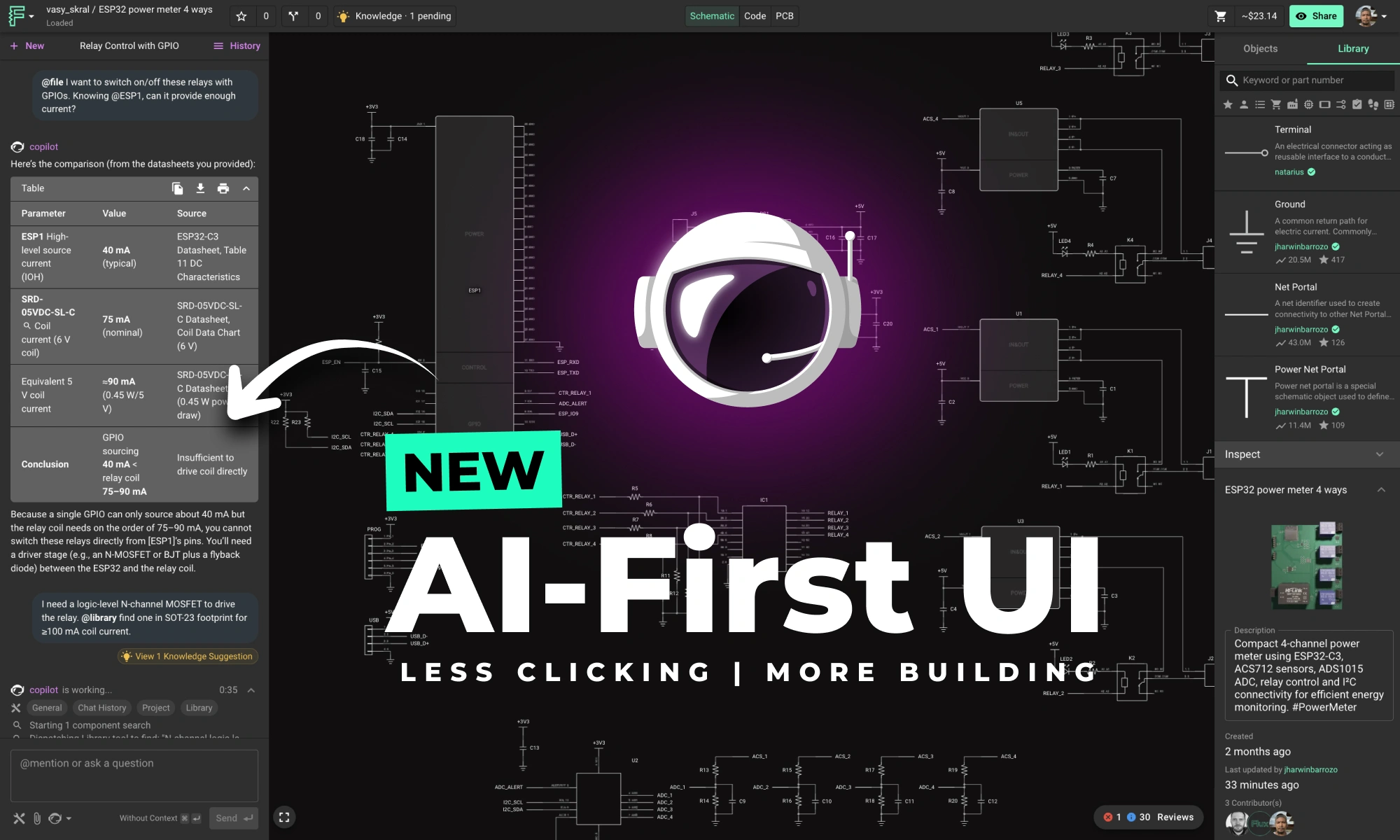
This update brings more than just polish—it’s the foundation for a faster, more fluid design experience, built around the way Copilot is used today and the way we see it evolving tomorrow.
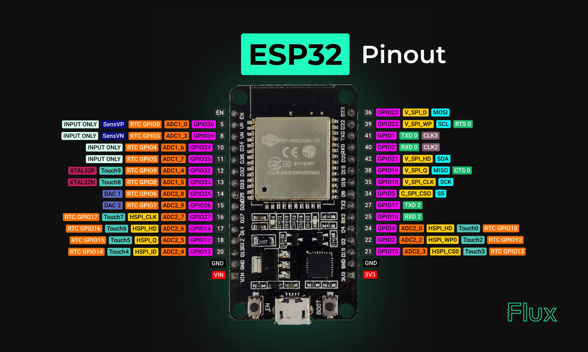
Looking for a comprehensive guide to ESP32 pinout? Check out our article that covers everything you need to know about the ESP32's pins, including digital, analog, PWM, and Strapping pins. Perfect for beginners and experts alike, our guide will help you understand the ESP32's pinout and how to use it in your projects.
Yes, the ESP32 has digital pins, also known as General Purpose Input/Output (GPIO) pins. These pins are used for digital input and output and can be configured as either inputs or outputs depending on the needs of the project. The ESP32 has a total of 36 GPIO pins that can be used for various purposes, including interfacing with sensors, controlling LEDs, and communicating with other devices.
NOTE: not all GPIOs are accessible in all development boards, but each specific GPIO works in the same way regardless of the development board you’re using. For ESP32 DEVKIT V1 board, GPIO6 to GPIO11 are connected to the integrated SPI flash and are not recommended for other uses.
The ESP32 is a 3.3V device, which means that all of its input and output pins are designed to operate with a maximum voltage of 3.3 volts. Connecting the ESP32 to a voltage source greater than 3.3 volts can damage the device, so it's important to use level shifters or voltage dividers when interfacing with higher voltage devices.
It's also important to note that the power supply for the ESP32 should be 3.3V DC. Some development boards or modules may have built-in voltage regulators that can accept a higher input voltage (such as 5V) and regulate it down to 3.3V for the ESP32, but it's always best to check the specifications of the specific device you are using to ensure proper voltage supply.
These pins don’t have internal pull-up or pull-down resistors. They can’t be used as outputs, so use these pins only as inputs:
To utilize these pins in Arduino IDE, and you want to make GPIO 22 as input and GPIO 23 as output:
{{insert-project-1-here}}
pinMode() configures the specified pin to behave either as an input (with or without an internal weak pull-up or pull-down resistor), or an output. It is possible to enable the internal pullup resistors with the mode INPUT_PULLUP. Additionally, the INPUT mode explicitly disables the internal pullups.
There are three serial ports on the ESP32 known as U0UXD, U1UXD and U2UXD all work at 3.3V TTL Level. There are three hardware supported serial interfaces on the ESP32 known as UART0, UART1 and UART2. Like all peripherals, the pins for the UARTs can be logically mapped to any of the available pins on the ESP32. However, the UARTs can also have direct access which marginally improves performance. The pin mapping table for this hardware assistance is as follows.
Strapping pins are used to put the ESP32 into bootloader or flashing mode. On most development boards with built-in USB to SERIAL, you don't need to worry about the state of these pins. The board itself puts the pins in the right state prior to flashing or when on boot mode.
Some GPIOs change their state to HIGH or output PWM signals at boot or reset. This means that if you have outputs connected to these GPIOs you may get unexpected results when the ESP32 resets or boots.
NOTE: If you have peripherals connected to these pins, you may encounter issues with trying to upload new code, flashing the ESP32 with new firmware, or resetting the board, it may be because those peripherals are preventing the ESP32 from entering the right mode.
{{insert-nico-video}}
The ESP32 has two I2C channels and any pin can be set as SDA or SCL. When using the ESP32 with the Arduino IDE, the default I2C pins are:
You can use the wire library to use other pins for I2C, you just need to call:
These are the default pin mapping for SPI
GPIO 6 to GPIO 11 are exposed in some ESP32 development boards. However, these pins are connected to the integrated SPI flash on the ESP-WROOM-32 chip and are not recommended for other uses. So, don’t use these pins in your projects:
{{insert-project-2-here}}
Goodnews. All ESP32 GPIO pins are interrupt-capable (interrupts) pins. You can enable the interrupt functionality to any GPIO input pin using this function from the Arduino Core.
Enable (EN) is the 3.3V regulator’s enable pin. It’s pulled up, so connect to ground to disable the 3.3V regulator. This means that you can use this pin connected to a pushbutton to restart your ESP32, for example.
The ESP32 has built-in Analog to Digital Converters (ADC) that allow it to convert analog signals into digital values that can be processed by the digital circuits on the chip. The ESP32 has a total of 18 ADC channels, which can be used to read analog signals from various sensors, such as temperature sensors, light sensors, and other types of sensors that output analog signals.
The ESP32's ADC has a resolution of 12 bits, which means that it can measure the analog signal and convert it into a digital value between 0 and 4095. The ADC can also be configured to sample the analog signal at different rates and can be programmed to read multiple channels simultaneously.
The ESP32 has 18 x 12 bits ADC input channels (while the ESP8266 only has 1x 10 bits ADC). These are the GPIOs that can be used as ADC and respective channels:
There are 2 x 8 bits DAC channels on the ESP32 to convert digital signals into analog voltage signal outputs. These are the DAC channels:
The ESP32 has 10 capacitive touch GPIOs. These GPIOs can sense variations in anything that holds an electrical charge, like the human skin. So they can detect variations induced when touching the GPIOs with a finger.
These pins can be easily integrated into capacitive pads, and replace mechanical buttons. Additionally, the touch pins can also be used as a wake up source when the ESP32 is in deep sleep.
To use the ESP32 touch sensor in Arduino:
Reading the touch sensor is straightforward. You use the touchRead() function, that accepts as argument, the GPIO you want to read.
This example arduino sketch reads the touch pin 0 and displays the results in the Serial Monitor.
{{insert-project-3-here}}
There is RTC GPIO support on the ESP32. The GPIOs routed to the RTC low-power subsystem can be used when the ESP32 is in deep sleep. These RTC GPIOs can be used to wake up the ESP32 from deep sleep when the Ultra Low Power (ULP) co-processor is running. The following GPIOs can be used as an external wake up source.
The ESP32 pulse width modulation PWM controller has 16 independent channels that can configured to generate PWM signals with different configuration and properties that can be used for controlling the intensity of digital signals, such as LEDs and Motors. PWM is a technique that allows the duty cycle of a digital signal to be varied, which in turn changes the average voltage and current delivered to the load.
The PWM frequency can be set using the ledcSetup() and ledcAttachPin() functions, which allow you to configure the PWM frequency and attach the PWM pin to a specific output.
In addition to the 16 hardware PWM pins, the ESP32 also supports software-based PWM, which can be used to control additional PWM channels on any GPIO pin. The ESP32's software PWM uses a technique called bit-banging, which allows the duty cycle of a digital signal to be varied by software.
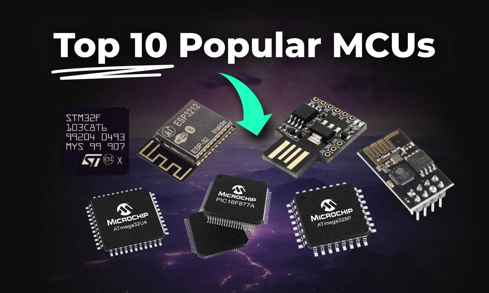
This article highlights 10 of the most popular microcontrollers, based on their usage in embedded systems, memory architecture, and the community support they enjoy.
This article highlights 10 of the most popular microcontrollers, based on their usage in embedded systems, memory architecture, and the community support they enjoy. Let’s dive in!
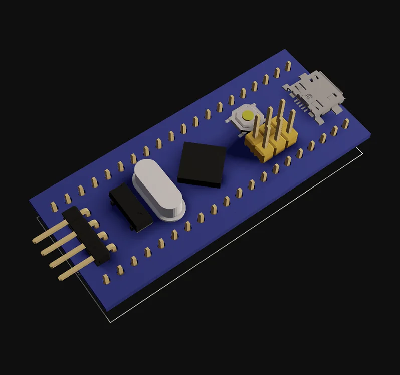
The STM32F103C8T6 is a versatile microcontroller with a 32-bit ARM Cortex-M3 core running at 72 MHz. It offers flash memory, non-volatile memory, and multiple peripherals like SPI, I²C, and CAN. Its performance makes it ideal for general-purpose embedded systems.
Key Features:
Development Board:
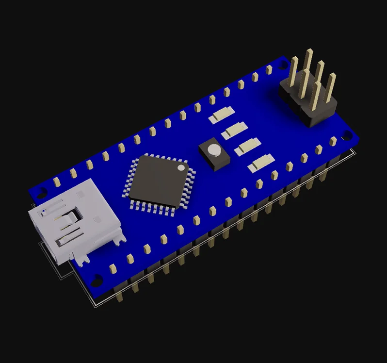
The ATmega328P, a popular Atmel microcontroller, powers many Arduino boards like the Uno. It offers easy programming through the Arduino IDE and features EEPROM for non-volatile memory storage. This microcontroller is great for beginners and general-purpose applications.
Key Features:
Development Boards:
The PIC16F877A is a Microchip microcontroller widely used for educational purposes. Its support for non-volatile memory and easy-to-use peripherals makes it an excellent choice for beginners.
Key Features:
Development Board:
The ATtiny85, another compact Atmel microcontroller, is ideal for small embedded systems. It supports SPI, I²C, and offers EEPROM for non-volatile memory.
Key Features:
Attiny85 ready-to-use module:
Development Boards:
The MSP430G2452 from Texas Instruments is known for low power operation, making it ideal for battery-powered embedded systems. It features essential peripherals and non-volatile memory.
Key Features:
Development Board:
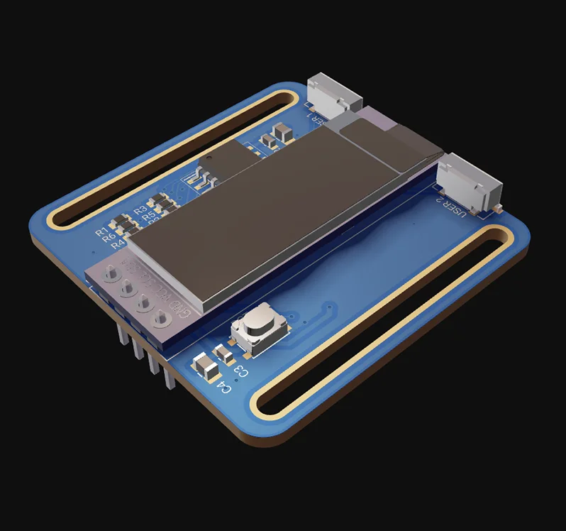
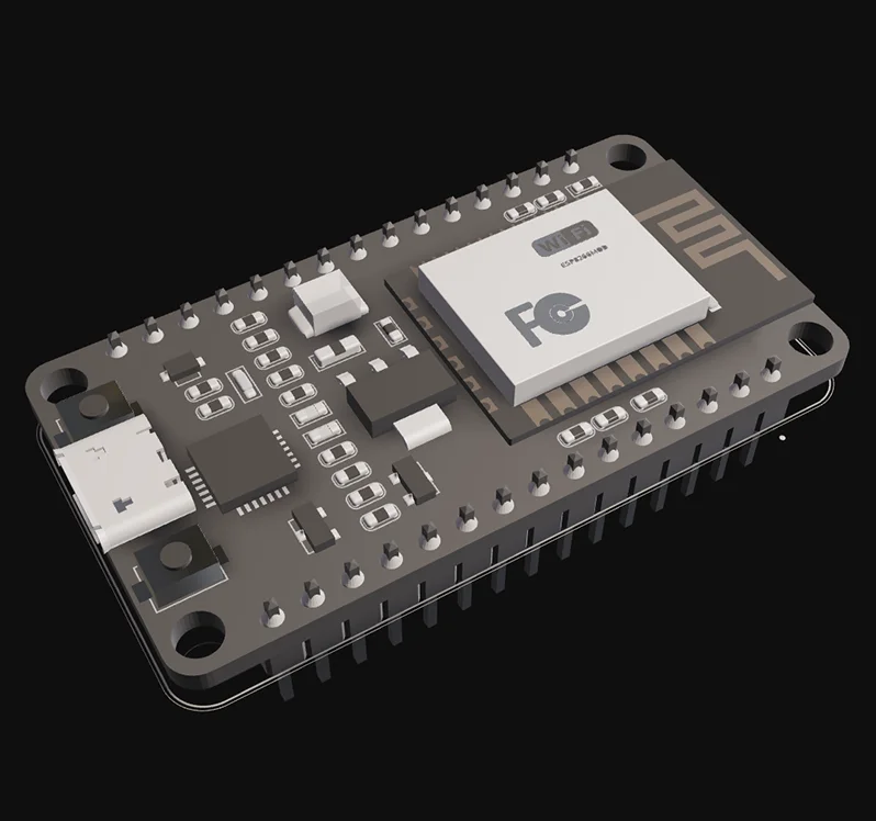
The ESP8266, a Microchip microcontroller, offers Wi-Fi connectivity and supports UART and SPI peripherals. It’s ideal for IoT projects and wireless applications.
Key Features:
Development Boards:
The ESP32 builds on the ESP8266 by adding dual-core processing and Bluetooth support. It is a powerful microcontroller for advanced embedded systems and general-purpose applications.
Key Features:
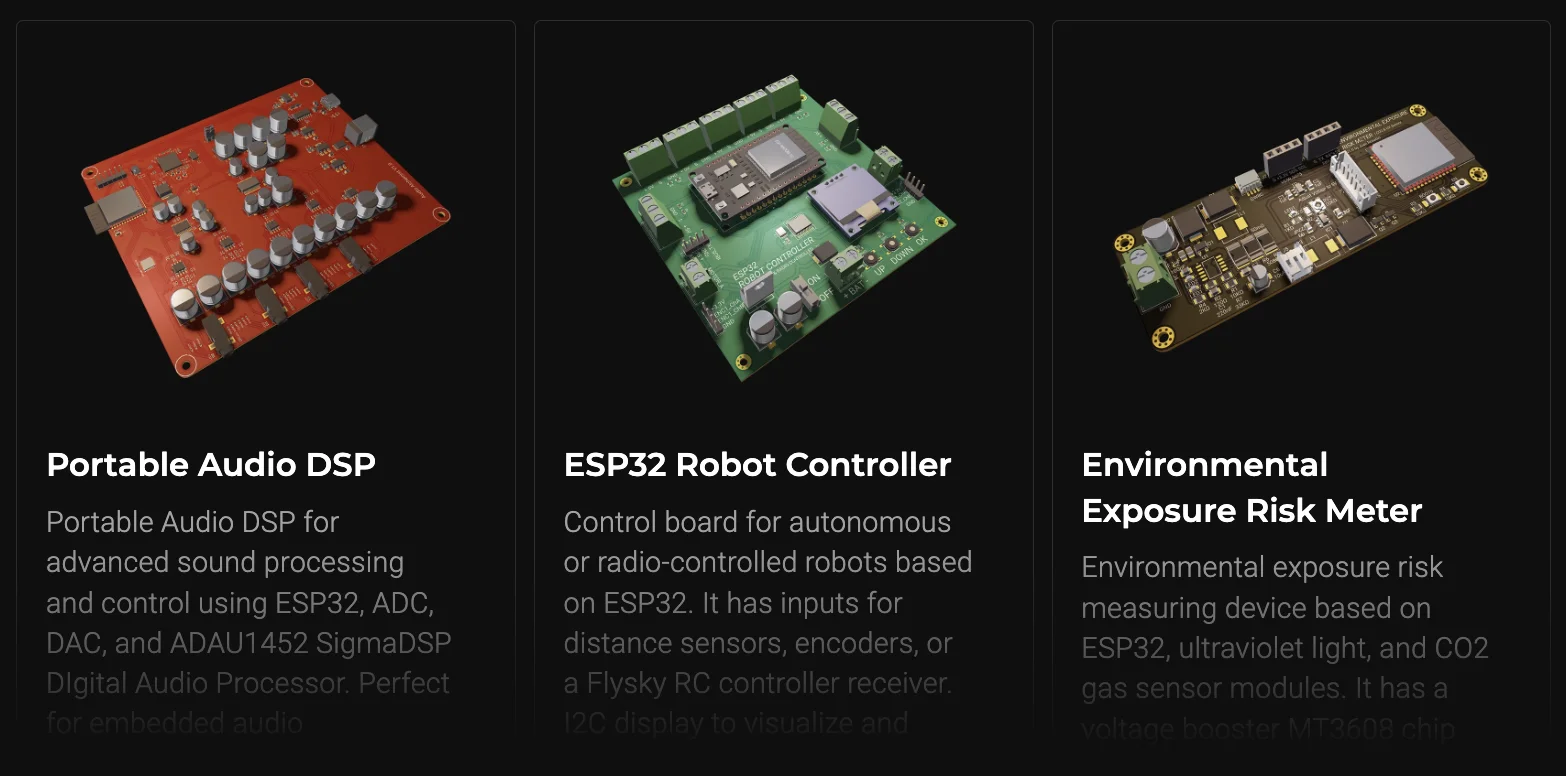
Curious about what you can build with the powerful ESP32 microcontroller? From smart home devices to IoT-based monitoring systems, the possibilities are endless! Check out some incredible ESP32 featured projects created by the Flux community, and get inspired to build your own.
Development Boards:
The ATmega32U4, another Atmel microcontroller, supports USB connectivity. It’s commonly used in custom keyboards and other embedded systems requiring serial communication.
Key Features:
Development Boards:
The STM8S103F3 is a reliable 8-bit microcontroller for industrial automation. It offers robust peripherals for control systems.
Key Features:
Development Boards:
The LPC1768 is a high-performance microcontroller with advanced connectivity peripherals like Ethernet and USB. It is suitable for demanding embedded systems.
Key Features:
Development Boards:
Every microcontroller listed here offers unique features for embedded systems. If you need low power operation, like the MSP430, or the wireless capability of the ESP32, there is a suitable MCU for every project. Choose wisely based on your project’s needs.
1. What is the meaning of MCUs?
MCUs (Microcontrollers) are compact integrated circuits that control specific functions in electronic devices. They contain a processor, memory, and input/output peripherals on a single chip, making them ideal for embedded systems, such as IoT devices, robots, and consumer electronics.
2. Which microcontroller is best for beginners?
The ATmega328 (Arduino Uno) is ideal due to its simplicity and community support.
3. What’s the difference between ESP8266 and ESP32?
The ESP32 offers dual-core processing, Bluetooth, and more advanced security features.
4. Which MCU is best for low power?
The MSP430 series is renowned for its ultra-low power consumption.
Whether you’re experimenting with an ATmega328 for your first Arduino project or building a cutting-edge ESP32-based IoT device, designing a custom PCB will take your project to the next level. Flux makes it easy with an intuitive interface, smart design tools, and access to a huge component library. No matter your experience level, Flux helps you create PCBs quickly and efficiently, without the usual headaches.
Get started today—sign up for Flux and bring your ideas to life!
Discover how CAD Librarians can leverage Flux’s key capabilities—AI Part Imports, Component Updates, Live Pricing, and JEP30 Export—each tailored to meet the specific demands of maintaining PCB libraries.
This post provides a detailed overview of how CAD Librarians can leverage Flux’s key capabilities—AI Part Imports, Component Updates, Live Pricing, and JEP30 Export—each tailored to meet the specific demands of maintaining PCB libraries. For more in-depth guidance, links to relevant sections of our documentation are provided.
Traditionally, librarians must manually extract and input data from component datasheets, which is not only labor-intensive but also prone to human error. Flux automates this process with its AI-driven part import feature, allowing you to parse datasheets directly into your library.
Learn how to do AI part imports in Flux.
Component lifecycle management is a major responsibility for CAD Librarians, as maintaining up-to-date libraries ensures that engineers are always working with the latest verified parts. With Flux, component updates are automatically managed, reducing manual effort and ensuring consistency across designs.
For detailed technical information, please refer to our documentation on component updates.
Component procurement is not just about ensuring technical compatibility—it’s also about balancing cost and availability. Flux integrates directly with supplier databases to provide live pricing and stock levels, which are visible directly within the part data.
Learn how Live Pricing works in more detail.
Flux's support for JEP30 export allows you to seamlessly integrate part data across multiple tools. The JEP30 format is widely accepted and enables you to transfer parts between different CAD platforms without losing data integrity.
Here's a detailed guide on how to use the JEP30 Export feature.
Flux offers a robust set of tools designed specifically to enhance your workflow as a CAD Librarian. By automating tasks like datasheet parsing and part updates, providing real-time supplier data, and ensuring compatibility across multiple platforms, Flux helps you streamline library management while reducing errors and ensuring design integrity.
For a more comprehensive look at Flux’s features, including how to integrate them into your workflow, check out our full documentation.
A case study: Learn how Agri-iO reimagined farm automation with custom hardware designed in Flux.
“Without Flux, it would have taken me months to master another tool. Flux made it possible to design my first board in just a few days, even while I was working a 9-to-5.”
– Michael van Niekerk, Co-Founder and Head of Technology, Agri-iO
Agri-iO is an agriculture-focused automation company that augments people's existing farming solutions with connected hardware and software. They aim to solve the problems faced by farmers who have unreliable GSM signals by automating pumps and monitoring water levels in remote areas. With Agri-iO’s solutions, anything on a farm can be automated and driven from one application, even when there's no Wi-Fi or LTE.
Agri-iO’s Co-Founder and Head of Technology, Michael van Niekerk, has a technical background, but at the onset of the company, he had never designed a PCB. So, when it came time for the team to develop their first product, off-the-shelf (OTS) electronics were the obvious solution.
Agri-iO designed its original products using Pycom’s LoPy devices. These products included automating existing irrigation pivots, tank and dam control, and pump automation. These devices were selected because of their MicroPython-enabled ESP32 chipset and support for LoRa, Wi-Fi, and BLE connectivity. With electronics in hand, Agri-iO wrote its MicroPython code, and the team was off to the races.
It wasn’t long before they started securing large contracts.
However, right before kicking off an important new project, Agri-iO discovered that Pycom was going out of business, and that meant their products were discontinued. Suddenly, Agri-iO was left without a hardware solution and a contract to fulfill.
“We were originally using Pycom's LoPy devices. But the company went bankrupt just before we got a big contract with Zambeef in Zambia, and we found ourselves left without a supply.”
– Michael van Niekerk, Co-Founder and Head of Technology, Agri-iO

At first, Agri-iO’s approach was to find a replacement OTS solution, but they quickly found that the right solution was hard to come by. Most OTS products they encountered supported C++, not MicroPython, and porting the original code proved to be too timely and costly.
So that left them with one option: designing custom hardware. But this wasn’t as straightforward as it sounded.
For starters, Agri-iO had a two-man technical team. Neither Michael nor Stephan Geldenhuys (another co-founder) had ever designed a PCB before. With no support or experience, the team began exploring design tools to pursue their own custom hardware.
However, they found that the design tools on the market were far from perfect. Some tools proved too expensive for a small startup like Agri-iO to afford. Other free tools proved too cumbersome and difficult to learn in a reasonable time, and they were up against a serious time crunch.
“I considered KiCad and Altium Designer, but Altium was too expensive. KiCad was not easy to use, and we didn’t have time to get past that learning curve. Flux was a few steps ahead in terms of ease of use, so we went with Flux.” – Michael van Niekerk, Co-Founder and Head of Technology, Agri-iO
In their research, Agri-iO came across Flux - and it quickly caught their eye.
Flux’s free-to-use nature was the first big draw. The company had limited resources, and a thousand-dollar EDA license was not an option. What proved more important, however, was Flux’s ease of use. Not only was Flux browser-based and compatible with any computing platform, but its extensive library of resources made it possible for the team to hit the ground running.
Shortly after finding Flux, the Agri-iO team came across Flux’s design tutorial and project built around Raspberry Pi’s RP2040. Features and Rust support made the RP2040 the perfect microcontroller for Agri-iO’s needs. So, the team simply forked the Flux example project, and they instantly had a major jump start on their custom design.

From there, the team leveraged Copilot’s guidance to fill in the blanks. Copilot helped them by providing example designs, suggesting components and configurations, and answering questions about which pins connected where.
In only a couple of days, Agri-iO went from a blank slate and no experience to a manufacturable custom hardware solution.
“I used Copilot to ask questions about which pins to connect and to get examples for specific designs. It suggested components and configurations. Copilot reduced the amount of review work needed, and overall, it was a wonderful experience.”
– Michael van Niekerk, Co-Founder and Head of Technology, Agri-iO

Thanks to Flux, Agri-iO successfully fulfilled its existing contracts and has since deployed dozens of units globally. At the beginning of their journey, the Agri-iO team had never designed a single PCB. Today, they’ve designed four custom boards, each of which is deployed in the field and has a major impact on the agricultural industry.
“Nothing was more satisfying than seeing our system working in the field, and we really have Flux to thank for it all. Now I can’t wait for our next batch of boards to arrive and to start shipping them out.”
– Michael van Niekerk, Co-Founder and Head of Technology, Agri-iO
Today, we’re launching automatic photorealistic 3D renderings so that you can put your best foot forward and share your work to the world. Now, anyone can effortlessly create stunning, dynamic, and professional 3D renders.
Steve Jobs once said “...there's just a tremendous amount of craftsmanship in between a great idea and a great product.” We agree wholeheartedly.
However, as PCB designers, it’s not always easy to demonstrate the thought and craftsmanship that went into your design. Other EEs might be able to appreciate your effort and understand the inner beauty of your work, but first, they’d need access to your design files and a compatible tool. Non-EEs may not understand the beautiful intricacies of your design, but they can appreciate a good layout and an aesthetically pleasant board.
In either case, we want to help you better demonstrate your craftsmanship. With automatic, realistic 3D renderings of your PCB, Flux is making this a reality.
Flux's new rendering capabilities automatically create the most realistic and beautiful representation of your design possible. No extra effort is needed to master rendering tools, and no experience is necessary. Now, anyone can effortlessly create stunning, dynamic, and professional 3D renders. And since Flux is browser-based and free to use, anyone can access your renders in real-time with just a link.
But why does this reality matter?
We understand that craftsmanship matters, detail counts, and extend that thinking to how you present your work. Login to your account to see how your projects look with the new rendering engine. 🚀
Discover how AI revolutionizes functional testing for PCB design. Learn to create comprehensive test plans faster with Flux Copilot, accelerating debugging processes and improving product quality.
With Flux, this dream is a reality. With Flux Copilot, you can leverage the power of AI to help you test and debug your circuit designs. Here are your steps and how AI can make this process easier.
Functional testing is the process of testing a mass-produced product to ensure that the high-level system functionality meets the design expectations. The goal is to ensure quality, but that’s not always straightforward.
As a functional testing team member, you’re often asked to develop test plans for products you have not designed and, therefore, have no experience with. Generally, you’re handed a set of design files and a product requirement document. Your task is to take that information and develop a thorough test plan to ensure the product meets all its requirements off the production line.
Generally, the hardest part is becoming familiar enough with the product to develop a comprehensive test plan. Historically, that means dozens of hours spent poring over schematics and layout files. But now, with AI, Flux is changing that narrative entirely.
With Flux Copilot, generating thorough functional test plans is a breeze. Here is what the process looks like
The process starts by importing your design files and product requirements document into Flux. Flux is compatible with design files from all of the major EDA tools, including Altium, Cadence, and KiCAD, so you can use Flux without having to change your tools.
Or, if your design is already native to Flux, simply input your product requirements document to get started.
Next, you should ask Copilot to help you determine what tests need to be run to ensure proper functionality.
Some of the most important questions to address in a test plan include
Copilot helps your team answer all of these questions by developing comprehensive and robust test plans for your design. Simply prompt Copilot with a question like
@copilot Create a comprehensive hardware design test plan for this project for the areas outlined in the testing and validation section. The goal is to ensure all components and circuits function correctly and reliably under specified conditions. Follow the steps:
- Provide a brief summary of the design, including the main functions and critical components of the schematic.
- Detail the requirement of that particular area for the design to work.
- Outline and explain the specific tests needed (with exact tools required where applicable) to verify performance of the hardware design. including test condition and expected behavior.
Once you have a test plan, want to ask Copilot to confirm that the current design is accordingly testable. That means ensuring all necessary signals have test points that can be probed in your testing efforts. You can ask Copilot something like
@copilot, clearly list if the right test points are present to fulfill this test plan.
Flux not only streamlines the testing and debugging process but also enhances the way test engineers and designers collaborate on projects.
In the event that the correct test points are not available, you can then use Flux’s collaboration tools. Simply leave a comment in the project file notifying the design owner of what signals need test points. With this kind of in-tool collaboration, everyone on the team can see the correspondence and the Copilot responses that elicited the design update.
By integrating collaboration within the design tool, Flux ensures that all team members have real-time access to test data, design changes, and analytical insights. This seamless integration allows for immediate feedback loops and faster decision-making, which is crucial when addressing complex design challenges
The final roadblock to fulfilling a testing plan is having the necessary equipment to carry it out. Testing plans often need accompanying testing rigs, which likely necessitate custom PCBs dedicated to these efforts.
Copilot can help by identifying what testing equipment might be necessary and then providing advice on designing that testing rig. Ask Copilot something like
@copilot, what other testing equipment is necessary to carry out this test plan?
If a custom PCB is required, Copilot can help with the process. Check out this design tutorial to learn more about creating custom PCBs with Copilot.
With Flux Copilot, your team can more easily develop comprehensive and thorough test plans that help catch design errors early in the process. This means your team can spend less time correcting errors and less money on unnecessary design revisions. Ultimately, that translates to higher quality products and faster time to market. Want to experience using AI to generate functional test plans? Sign up for Flux today.