In this post, we’ll show you exactly how to unlock the power of Flux Copilot for yourself: from writing rock-solid triggers to scoping entries at the project, user, and system levels.
Describes Flux.ai's process of enabling 'noUncheckedIndexedAccess' in their TypeScript codebase. This setting enhances type safety by enforcing checks for possible 'undefined' values but introduces numerous type errors in a large codebase. To manage this, Flux.ai used heuristics and automation to suppress new errors with '!' and automate fixes using a provided script.
Flux.ai was started around 3 years ago in TypeScript with the default compiler settings. If we could go back in time, there is one setting we would surely change: noUncheckedIndexedAccess. By default, this setting is false. Many people believe it should be true.
What does noUncheckedIndexedAccess do? By default, TypeScript assumes any array element or object property you access dynamically actually exists:
In the example above, the function will throw an error if the string is empty, because str[0] returns undefined and doesn't have a toUpperCase function. TypeScript doesn't warn you about that, regardless of whether strict mode is enabled or not. This is a huge hole in type safety.
The flag noUncheckedIndexedAccess will plug that hole and force you to deal with the possible undefined:
So, why can't we just turn on noUncheckedIndexedAccess? You can, but in a large codebase like that of Flux.ai, you are likely to get thousands of type errors. We had 2761 errors across 373 files! For one speedy engineer converting one file every minute, it would have taken 6+ hours of mind-numbing work to convert all 373 files.
The solution we describe here is how to smoothly convert your codebase with some simple heuristics and automation.
According to Wikipedia, a heuristic technique
is any approach to problem solving or self-discovery that employs a practical method that is not guaranteed to be optimal, perfect, or rational, but is nevertheless sufficient for reaching an immediate, short-term goal or approximation.
That is definitely true here.
The goal was to get the codebase compiling with the new flag, not to fix any bugs. The fixing can come later.
To that end, we intentionally added type assertions ! to suppress all new type errors from undefined types without changing the runtime behavior of the code.
Expanding the scope of replacements to preceding lines allowed us then to automate more fixes with few false positives.
The full script we ran on our codebase is below. Note: it did not fix all the errors. It fixed around 2400 out of 2761 errors, leaving around 100 files for us to fix by hand.
Pro-tip: when experimenting with the replacers and precede, you can simply reset your changes with git reset --hard HEAD (assuming you are working in a git repo).
In this blog post, we explore how Flux.ai effectively uses Web Workers and ImmerJS to enhance data replication in our web-based EDA tool. We discuss our challenges with data transfer, our exploration of SharedArrayBuffer, and our ultimate solution using ImmerJS patches.
Web Workers are an established browser technology for running Javascript tasks in a background thread. They're the gold standard for executing long-running, CPU-intensive tasks in the browser. At Flux.ai, we successfully harnessed Web Workers, paired with ImmerJS patches, to minimize data transfer and deliver an ultra-fast user experience. This post will take you through our journey of using Web Workers and ImmerJS for data replication in our web-based EDA tool.
Flux.ai, an innovative web-based EDA tool, needs to compute the layout of thousands of electronic components simultaneously for its unique PCB layouting system. This process must adhere to user-defined rules. Our initial prototype revealed that layouting could take several seconds, leading us to explore the capabilities of Web Workers to parallelize this process and unblock the UI.
At bottom, the web worker API is extremely simple. A single method, postMessage, sends data to a web woker, and the same postMessage method is used to send data back to the main thread. We use a popular abstraction layer on top of postMessage, Comlink, developed several years ago by Google, that makes it possible to call one of your functions in a web worker as if it existed in the main thread. Newer, better or similar abstractions may exist. We did learn in using Comlink that it can easily blow up your JavaScript bundle size.
The trouble with using a web worker in a pure RPC style is that you most likely have a lot of data to pass through postMessage which is as slow as JSON.stringify, as a rule of thumb. This was definitely true in our case. We calculated that it would take 100ms at our desired level of scale just to transfer the layouting data each way, eating into the benefit of a parallel web worker.
A potential solution to the data transfer problem could be using SharedArrayBuffer, recommended for use with web workers. However, SharedArrayBuffer "represents a generic raw binary data buffer" meaning that a) it is of fixed size and b) it does not accept JS objects, strings, or other typical application data. Our investigations led us to conclude that the performance benefits were offset by the encoding and decoding costs in SharedArrayBuffer. One hope for the future is a Stage 3 ECMAScript proposal for growable ArrayBuffers.
We decided instead to populate our web worker with all the data on initial load of a Flux document (while the user is already waiting) and update it with changes as they happened. An added benefit of this approach is that the functions designed to run inside the web worker can also be run in the main thread with the flip of a global variable. You might want to do this for Jest tests, for example, which do not support web workers by default.
We got our changes in document data from ImmerJS, something we were already using as part of Redux Toolkit. Immer is an extremely popular library that enables copy-on-write for built-in data types via a Proxy. A lesser-known feature of Immer is Patches. The function produceWithPatches will return a sequence of patches that represent the changes to the original input.
We made a function that wraps produceWithPatches and assigns the patches back into the document for use downstream.
With the patches in hand, we could then complete our data flow from main thread to web worker and back again. The main thread calls the worker functions from middleware after every global state change. In Flux, we use redux-observable middleware.

In the code, the relevant functions look like this, assuming you are using Comlink.
The result of our use of Web Workers and ImmerJS patches was a significant reduction in workload on every document change and the ability for users to continue interacting with the application during a large re-layout - a priceless benefit in our web-based EDA tool.
For extra speed in our web worker, we forked the Immer applyPatches function. The original version was too slow for our needs. So, we adapted applyPatches to skip the draft step and mutate the target object in-place, resulting in a 10X speedup.
In conclusion, Web Workers and ImmerJS have proven to be powerful tools for efficient data replication in Javascript, particularly in the context of our web-based EDA tool, Flux.ai. They offer a potent combination for handling complex, CPU-intensive tasks, and improving user experience through faster data transfer and processing.
CO2 sensors monitor air quality, helping prevent cognitive decline from high CO2 levels. They use various technologies for accuracy in different settings. These sensors are vital for health, efficiency, and safety.
Imagine sitting in a classroom for hours. The air feels stale. You struggle to focus. What you might not realize is that carbon dioxide levels have likely doubled since you entered the room. This invisible gas affects your cognitive function, and a CO2 sensor is the only reliable way to detect these changes before they impact your health and performance.
A CO2 sensor is a device that measures carbon dioxide concentration in air, typically expressed in parts per million (ppm). These sensors convert the presence of CO2 molecules into electrical signals that can be read and interpreted.
Accurate CO2 measurement matters for three main reasons:
Several technologies power modern CO2 sensors, each with distinct operating principles and applications. Let's examine how they work and where they excel.
CO2 levels above 1000 ppm can reduce cognitive function by 15%. At 2500 ppm, that reduction jumps to 50%. These aren't just numbers—they translate to real productivity losses in offices, schools, and homes.
Beyond health concerns, CO2 sensors enable demand-controlled ventilation systems that can cut HVAC energy costs by 5-15%. They also help facilities meet indoor air quality standards required by building codes and health regulations.
CO2 readings serve as a proxy for overall air quality and ventilation effectiveness. When CO2 rises, it suggests other pollutants may be accumulating too.
NDIR sensors work on a simple principle: CO2 absorbs infrared light at a specific wavelength (4.26 microns). The sensor shines infrared light through a sample chamber. The more CO2 present, the less light reaches the detector.
Key components include:
NDIR sensors offer excellent accuracy (±30 ppm) and longevity (10+ years) but tend to be larger and more expensive than alternatives.
Photoacoustic sensors use a clever approach: when CO2 absorbs infrared light, it heats up and expands slightly, creating pressure waves. A sensitive microphone detects these tiny sound waves, which correlate to CO2 concentration.
The system includes:
These sensors can be very sensitive and work well in challenging environments, but their complexity makes them less common in consumer applications.
Chemical sensors detect CO2 through reactions that change electrical properties of materials. For example, metal oxide semiconductors change resistance when exposed to CO2.
While generally more affordable and compact than NDIR sensors, chemical sensors typically offer lower accuracy (±100 ppm) and require more frequent calibration. They're common in lower-cost applications where approximate readings are sufficient.
A complete CO2 sensor system extends beyond the detection element to include:
Modern sensors often include microcontrollers that handle calibration, error correction, and data formatting. Flux's sensor component library includes many CO2 sensors with these integrated features.
Several factors can impact sensor readings:
Quality sensors incorporate compensation for these variables, but understanding these limitations helps in selecting and positioning sensors appropriately.
In buildings, CO2 sensors trigger ventilation systems when levels rise, bringing in fresh air only when needed. This approach can reduce energy consumption while maintaining air quality.
Smart building systems use CO2 data to optimize occupancy patterns and ventilation schedules. Some advanced systems even predict CO2 trends based on historical patterns.
Plants consume CO2 during photosynthesis. In greenhouses, maintaining optimal CO2 levels (often 1000-1500 ppm) can increase crop yields by 20-30%.
CO2 sensors control enrichment systems that release additional carbon dioxide during daylight hours. Flux's greenhouse control system demonstrates how these sensors integrate with environmental controls.
In industrial settings, CO2 sensors detect leaks from process equipment or storage tanks. They trigger alarms when levels exceed safety thresholds (typically 5,000+ ppm).
Environmental monitoring networks use CO2 sensors to track emissions and verify compliance with regulations. These applications often require higher precision and reliability.
Research applications demand the highest accuracy, often ±1-5 ppm. These sensors undergo rigorous calibration against certified reference gases.
Labs use CO2 sensors to monitor incubators, controlled environment chambers, and experimental setups where precise gas composition matters.
When selecting a CO2 sensor, consider:
For reliable operation, place sensors away from direct air currents, heat sources, and areas where people might breathe directly on them. Regular calibration—at least annually for critical applications—maintains accuracy.
The CO2 sensor market is evolving rapidly. Watch for:
Integration with environmental data logging systems will make CO2 data more actionable through analytics and automation.
CO2 sensors have evolved from specialized scientific instruments to essential components in smart buildings, agriculture, and safety systems. As costs decrease and capabilities improve, expect to see these devices becoming as common as smoke detectors—silent guardians of the air we breathe.
Ready to experience the benefits of CO2 monitoring firsthand? Get started for free with Flux today and take the first step towards smarter, healthier environments. Don’t wait—join the growing community embracing innovative air quality solutions now!
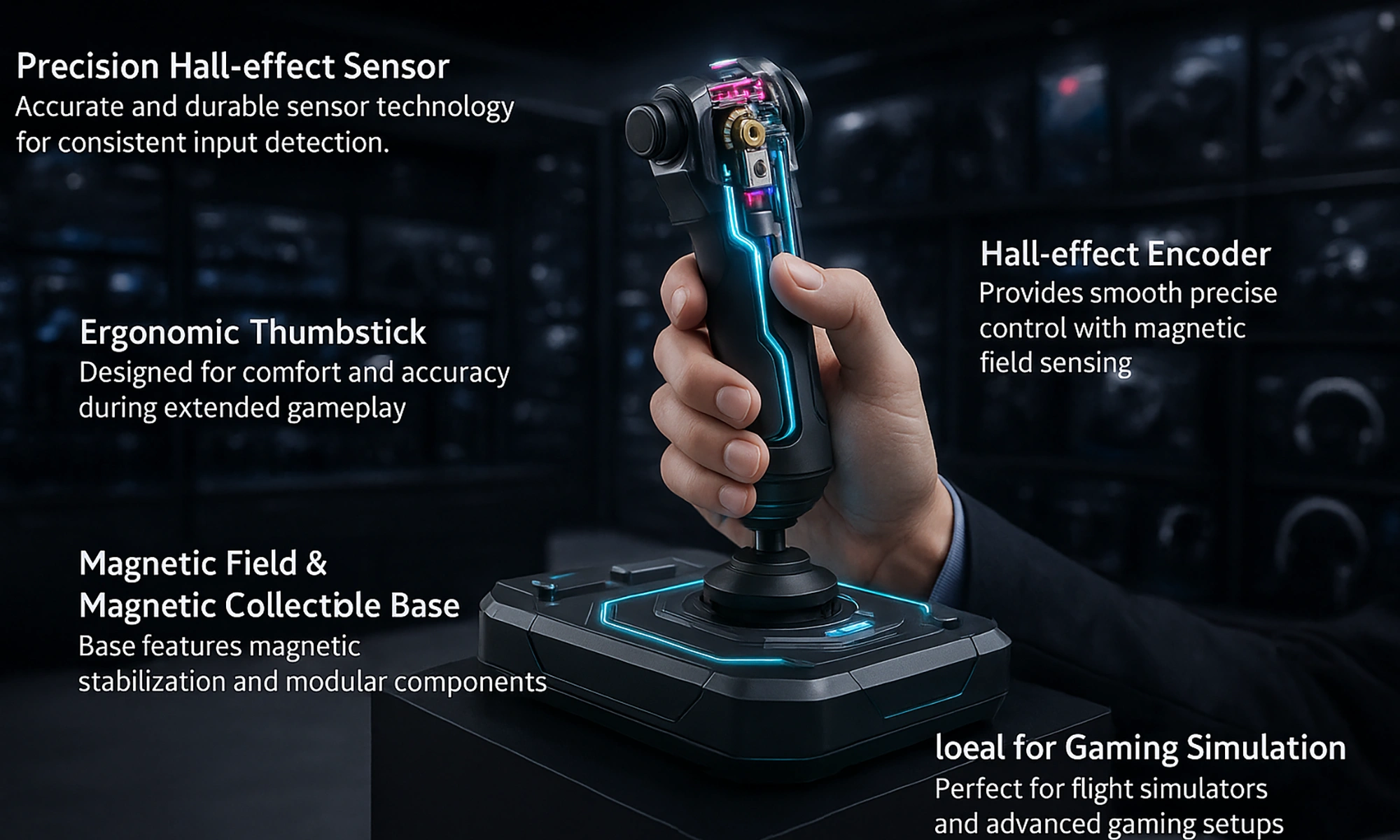
Hall effect joysticks use magnetic sensors for precise, durable, and contactless control. They outperform traditional joysticks in gaming, robotics, and industry.
Imagine controlling a surgical robot where movement accuracy down to fractions of a millimeter matters. Or picture yourself in a competitive gaming scenario where the slightest input error costs you the match. This level of precision is what hall effect joysticks provide.
A hall effect joystick is an input device that uses magnetic sensors to track movement without physical contact between components. This technology has changed how we interact with everything from gaming controllers to industrial equipment.
A hall effect joystick uses magnetic sensors to detect position changes. Unlike traditional potentiometer joysticks that rely on physical contact between components, hall effect joysticks work through magnetic field detection.
Traditional joysticks wear down as their mechanical parts rub against each other. This creates dead zones and drift over time. Hall effect joysticks eliminate these problems by removing the physical contact points. The result? Better accuracy and a much longer lifespan.
You'll find these joysticks in applications that need high precision: gaming controllers, medical equipment, industrial controls, and flight simulators.
The hall effect principle is simple but powerful. When a magnetic field passes through a semiconductor with current flowing, it creates a voltage perpendicular to both the current and magnetic field. This voltage can be measured to determine the magnet's position.
In a joystick, magnets attach to the moving stick while sensors remain fixed on the circuit board below. As you move the stick, the changing magnetic field position creates varying voltage outputs that precisely track movement in all directions.
This contactless design means no parts wear against each other, eliminating the mechanical drift that plagues traditional joysticks.
A typical hall effect joystick consists of:
The PCB contains signal conditioning circuits that convert raw sensor data into clean, usable signals. Voltage regulators ensure stable operation across different power conditions.
Hall effect joysticks provide analog outputs that map to position data with remarkable precision. While a standard potentiometer joystick might offer 8-bit resolution (256 positions per axis), hall effect models often deliver 10-bit (1024 positions) or 12-bit (4096 positions) resolution.
This high resolution lets you make tiny, controlled movements that standard joysticks simply can't detect.
The contactless operation of hall effect joysticks means they don't wear out like traditional models. A typical potentiometer joystick might last 1-2 million cycles before developing issues. Hall effect joysticks routinely handle 10+ million cycles with no degradation in performance.
This durability reduces maintenance needs and replacement costs over time.
Hall effect joysticks resist environmental factors that damage traditional joysticks:
These qualities make them ideal for industrial controls and outdoor applications where conditions are harsh.
Premium gaming controllers now feature hall effect joysticks to eliminate drift and extend controller life. Gamers report smoother aim in first-person shooters and more consistent control during long gaming sessions.
The technology has become particularly valuable in competitive gaming where precision can make the difference between winning and losing.
In robotics, hall effect joysticks provide the precise control needed for delicate operations. Industrial equipment operators benefit from consistent performance even in harsh factory environments.
The reliability factor is critical in these settings where equipment downtime costs money and may create safety risks.
Drone pilots and RC enthusiasts value the fine control hall effect joysticks provide. Flight simulators use them to recreate the precise feeling of aircraft controls.
Their lightweight design and low power requirements make them ideal for portable control systems.
When selecting a hall effect joystick, consider:
Look for these key specifications in datasheets:
Lower hysteresis values and high linearity percentages indicate better performance.
Connecting a hall effect joystick to your project is straightforward:
You can design your PCB to integrate directly with these joysticks using A Better Way to Build PCBs | Flux, which helps streamline the design process.
Basic calibration involves:
For robot control projects, you might find the ESP32 robot controller design particularly helpful as a reference.
To clean up joystick signals:
Though hall effect joysticks need less maintenance than traditional ones, you should:
If you experience problems:
Recalibrate your joystick when:
The technology continues to evolve. We're seeing development of:
These joysticks will play an important role in VR controllers and IoT devices where precise physical input matters.
Hall effect joysticks provide unmatched precision and durability for your electronics and gaming projects. Their contactless magnetic sensing eliminates the wear issues that plague traditional joysticks while delivering higher resolution and better environmental resistance.
Whether you're building a gaming controller, robot, or industrial system, these joysticks offer the reliability and precision you need. And with proper selection and integration, they'll continue performing accurately long after traditional joysticks would have failed.
For your next electronics project, consider how a hall effect joystick might improve your user experience and system reliability.
Ready to bring your project to life? Get started for free with flux.ai — the perfect platform to design, simulate, and prototype your electronics with ease.
The SNES controller revolutionized gaming with its ergonomic shape, responsive buttons, and innovative shoulder controls. Its design set the standard for modern controllers. Even today, it remains a blueprint for comfort and precision in input devices.
Nintendo made a bold move away from the boxy NES controller with the SNES pad. The new "dog bone" shape measured approximately 2.4" (61 mm) in height and 5.67" (144 mm) in width, creating a form that fit naturally in players' hands. This wasn't just about looks—it addressed a real problem.
Nintendo moved away from the not-so ergonomic brick shape of the NES controller to provide a slicker design, and this layout laid the groundwork for future controllers.
Hand fatigue plagued gamers during long play sessions with the NES controller. The SNES design solved this with rounded edges and a contoured shape that distributed pressure more evenly across the palms. The controller's weight balance kept it steady during intense gameplay without causing wrist strain.
The surface texture provided just enough grip without feeling rough. This subtle detail prevented the controller from slipping during sweaty gaming marathons—a common issue with earlier controllers.
The SNES D-pad refined Nintendo's cross-shaped directional control with a precise pivot mechanism. A central fulcrum point allowed the pad to rock in eight directions while maintaining accuracy. Under the hood, the design featured specific measurements that created its distinctive feel—the dome gap measured .7mm while the contact gap was 1mm, creating a .3mm difference that delivered the perfect balance of resistance and responsiveness.
This design provided tactile feedback that let players know exactly when they'd registered a directional input—critical for platformers and fighting games where timing and precision determined success.
The diamond arrangement of A, B, X, and Y buttons marked a significant evolution from the NES controller's two-button layout. These buttons used silicone dome switch technology that created a satisfying tactile response when pressed.
Nintendo Fandom describes the diamond layout as part of the SNES's "rounded dog-bone like design" that added X and Y buttons. The US version featured an interesting design choice: concave X and Y buttons paired with convex A and B buttons, while the Japanese Super Famicom version had all convex buttons. This subtle difference helped players orient their thumbs without looking down at the controller.
Each button press collapsed a rubber dome, bringing a conductive pad into contact with traces on the circuit board. This mechanism required just enough force to prevent accidental presses while remaining responsive enough for rapid-fire actions.
Perhaps the most forward-thinking feature was the addition of L and R shoulder buttons. These buttons used a pivot assembly design that was completely different from the face buttons.
As noted on Printables.com, some versions pivot on a metal rod while others use molded plastic, and a Digital Press forum post confirms both variations exist. This pivot mechanism created a longer travel distance and a progressive resistance that foreshadowed the triggers that would become standard in later controllers.
The placement at the top edge of the controller allowed players to maintain their grip while accessing additional inputs—a revolutionary concept that expanded the possibilities for game controls.
The SNES controller's 12-bit shift register multiplexed all button signals through a single data line—an elegant engineering solution that simplified the internal wiring while allowing for more inputs.
With eight inputs including Start and Select, the SNES controller enabled complex combinations that previous controllers couldn't support. Players could comfortably press up to four buttons simultaneously, opening new gameplay possibilities for developers.
The controller's influence spread throughout the industry. The diamond button arrangement and shoulder buttons appeared in countless subsequent controllers, from the PlayStation to modern gamepads.
Less obvious innovations included thoughtful cable routing through strain relief pins, which prevented wire damage at the connection point. The modular screw assembly made repairs straightforward—though some later models like the SNS-102 had soldered cables that reduced this benefit.
A great example of how this classic design can be adapted today is demonstrated in a sample SNES project made with Flux. You can explore the project here, showcasing a SNES controller Arduino Nano shield.
The SNES controller's design principles have become industry standards. The ergonomic shape, multi-button layout, and shoulder buttons appear in virtually every modern controller.
Retro gaming and speedrunning communities still prize original SNES controllers for their authentic feel and precision. The demand has spawned a market for high-quality replicas that maintain the classic design while adding modern features like wireless connectivity. As noted in a Retro-Bit Legacy 16 review, "The Switch Online SNES library of games also beg to be played with a SNES-styled controller!".
Even Nintendo's own Switch controllers for playing SNES games in their online library draw directly from the original design—proof that some engineering solutions stand the test of time.
The SNES controller remains relevant because it solved fundamental problems in human-computer interaction. It found the sweet spot between complexity and usability, between comfort and control. These principles continue to guide controller design today, making the SNES pad not just a nostalgic artifact but a blueprint for effective gaming input devices.
For hardware engineers looking to apply these time-tested principles to modern designs, Flux.ai's browser-based EDA platform offers powerful tools. With AI Auto-Layout and Flux Copilot, you can quickly prototype input devices that incorporate the SNES controller's ergonomic brilliance while leveraging modern components and manufacturing techniques—all without installing specialized software.
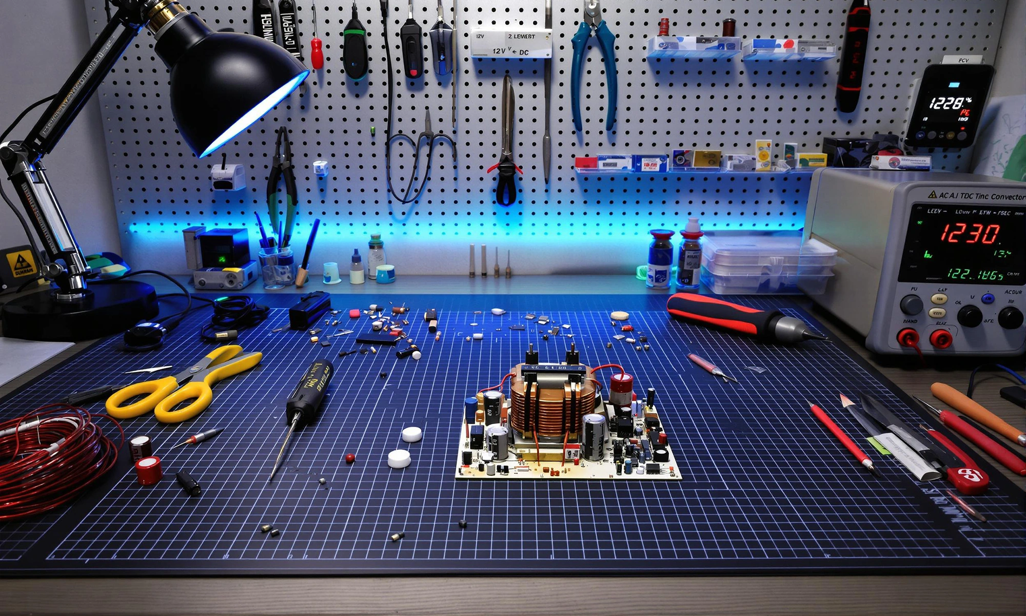
AC to DC converters transform wall power into the stable DC voltage electronics need. They work by rectifying AC, filtering ripples, and regulating output. These converters power everything from phones to server racks and are evolving with efficient, compact technologies.
On Flux.ai's browser-based EDA platform, you can design and route your power converter PCBs with AI Auto-Layout and real-time assistance from Flux Copilot—no installations required.
An AC to DC converter (also called a rectifier) is an electronic circuit that transforms alternating current, which periodically changes direction, into direct current that flows in only one direction. Rectification is the conversion of alternating current (AC) to direct current (DC). This conversion is essential because most electronic components—from microprocessors to LEDs—require DC power to function properly.
The first step in AC to DC conversion is rectification. This process uses diodes—electronic components that allow current to flow in only one direction—to convert AC into pulsating DC. As explained by GeeksforGeeks, diodes act like one-way valves for electricity.
Two main types of rectifiers exist:
Full-wave rectification is more efficient as it uses the entire input waveform rather than discarding half of it. Another fascinating project to explore is the Brave Power Management Board, which showcases advanced power management techniques and practical applications in electronics.
After rectification, the DC output still contains significant voltage ripples. Filtering smooths these ripples using capacitors and inductors:
A typical filter often uses large electrolytic capacitors across the rectifier output to reduce ripple voltage. This is commonly followed by LC (inductor-capacitor) networks, which provide additional smoothing by further filtering out fluctuations. Key points about LC filter design include the use of inductors to block high-frequency noise and capacitors to bypass it, resulting in a cleaner DC output. Proper selection of component values is essential to achieve the desired filtering performance.
The final step ensures a stable output voltage regardless of input fluctuations or load changes. Two main regulator types exist:
Modern designs often favor switching regulators for their efficiency, especially in battery-powered devices. You can explore various voltage regulator options in our parts library.
A typical AC to DC converter contains:
Different applications require different converter types:
You can explore our power management reference designs.
When designing AC to DC converters, pay attention to:
For PCB layout tips to minimize EMI/EMC, consider the following important guidelines:
These practices help ensure optimum performance and compliance with EMI/EMC standards, especially in power management systems and other high-power designs.
Common problems and solutions include:
For complex designs, systematic debugging and simulation can save hours of troubleshooting time. A summarized guide for troubleshooting DC power supplies includes checking the power source, verifying connections, measuring output voltage and current, inspecting for overheating components, and using simulation tools to identify faults before physical testing.
The field continues to advance with:
These technologies are making converters smaller, more efficient, and more reliable than ever before.
AC to DC converters form the foundation of modern electronics, transforming wall power into the clean DC voltages our devices need. From simple phone chargers to complex industrial systems, the basic principles remain the same: rectify, filter, and regulate.
Ready to accelerate your power supply design? Sign up for a free Flux.ai account or request a custom demo today. Our browser-based tools eliminate installation headaches while providing powerful design capabilities powered by AI.
Join our Slack community or browse the Flux docs for step-by-step tutorials and design tips.