May 15, 2025
What Is an AC to DC Converter? Technical Basics Explained
Share
BuildWithFlux


A curated collection of PCB and hardware projects crafted by our talented Flux community.
On Flux.ai's browser-based EDA platform, you can design and route your power converter PCBs with AI Auto-Layout and real-time assistance from Flux Copilot—no installations required.
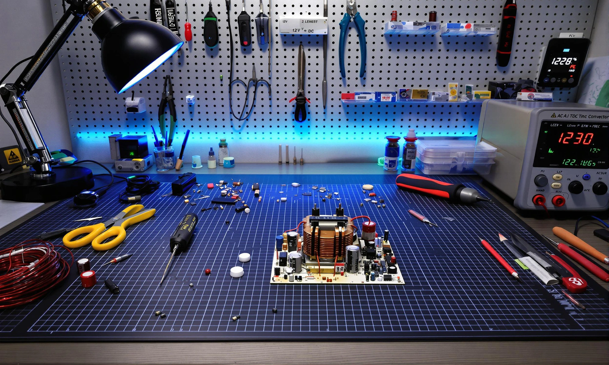
An AC to DC converter (also called a rectifier) is an electronic circuit that transforms alternating current, which periodically changes direction, into direct current that flows in only one direction. Rectification is the conversion of alternating current (AC) to direct current (DC). This conversion is essential because most electronic components—from microprocessors to LEDs—require DC power to function properly.
The first step in AC to DC conversion is rectification. This process uses diodes—electronic components that allow current to flow in only one direction—to convert AC into pulsating DC. As explained by GeeksforGeeks, diodes act like one-way valves for electricity.
Two main types of rectifiers exist:
Full-wave rectification is more efficient as it uses the entire input waveform rather than discarding half of it. Another fascinating project to explore is the Brave Power Management Board, which showcases advanced power management techniques and practical applications in electronics.
After rectification, the DC output still contains significant voltage ripples. Filtering smooths these ripples using capacitors and inductors:
A typical filter often uses large electrolytic capacitors across the rectifier output to reduce ripple voltage. This is commonly followed by LC (inductor-capacitor) networks, which provide additional smoothing by further filtering out fluctuations. Key points about LC filter design include the use of inductors to block high-frequency noise and capacitors to bypass it, resulting in a cleaner DC output. Proper selection of component values is essential to achieve the desired filtering performance.
The final step ensures a stable output voltage regardless of input fluctuations or load changes. Two main regulator types exist:
Modern designs often favor switching regulators for their efficiency, especially in battery-powered devices. You can explore various voltage regulator options in our parts library.
A typical AC to DC converter contains:
Different applications require different converter types:
You can explore our power management reference designs.
When designing AC to DC converters, pay attention to:
For PCB layout tips to minimize EMI/EMC, consider the following important guidelines:
These practices help ensure optimum performance and compliance with EMI/EMC standards, especially in power management systems and other high-power designs.
Common problems and solutions include:
For complex designs, systematic debugging and simulation can save hours of troubleshooting time. A summarized guide for troubleshooting DC power supplies includes checking the power source, verifying connections, measuring output voltage and current, inspecting for overheating components, and using simulation tools to identify faults before physical testing.
The field continues to advance with:
These technologies are making converters smaller, more efficient, and more reliable than ever before.
AC to DC converters form the foundation of modern electronics, transforming wall power into the clean DC voltages our devices need. From simple phone chargers to complex industrial systems, the basic principles remain the same: rectify, filter, and regulate.
Ready to accelerate your power supply design? Sign up for a free Flux.ai account or request a custom demo today. Our browser-based tools eliminate installation headaches while providing powerful design capabilities powered by AI.
Join our Slack community or browse the Flux docs for step-by-step tutorials and design tips.


Imagine an AI teammate that doesn’t just chat about your PCB ideas, but actively transforms them into schematics—placing parts, connecting circuits, and optimizing your design at your command, all through natural language. That’s exactly what the newly overhauled Flux Copilot does.

This article highlights 10 of the most popular microcontrollers, based on their usage in embedded systems, memory architecture, and the community support they enjoy.
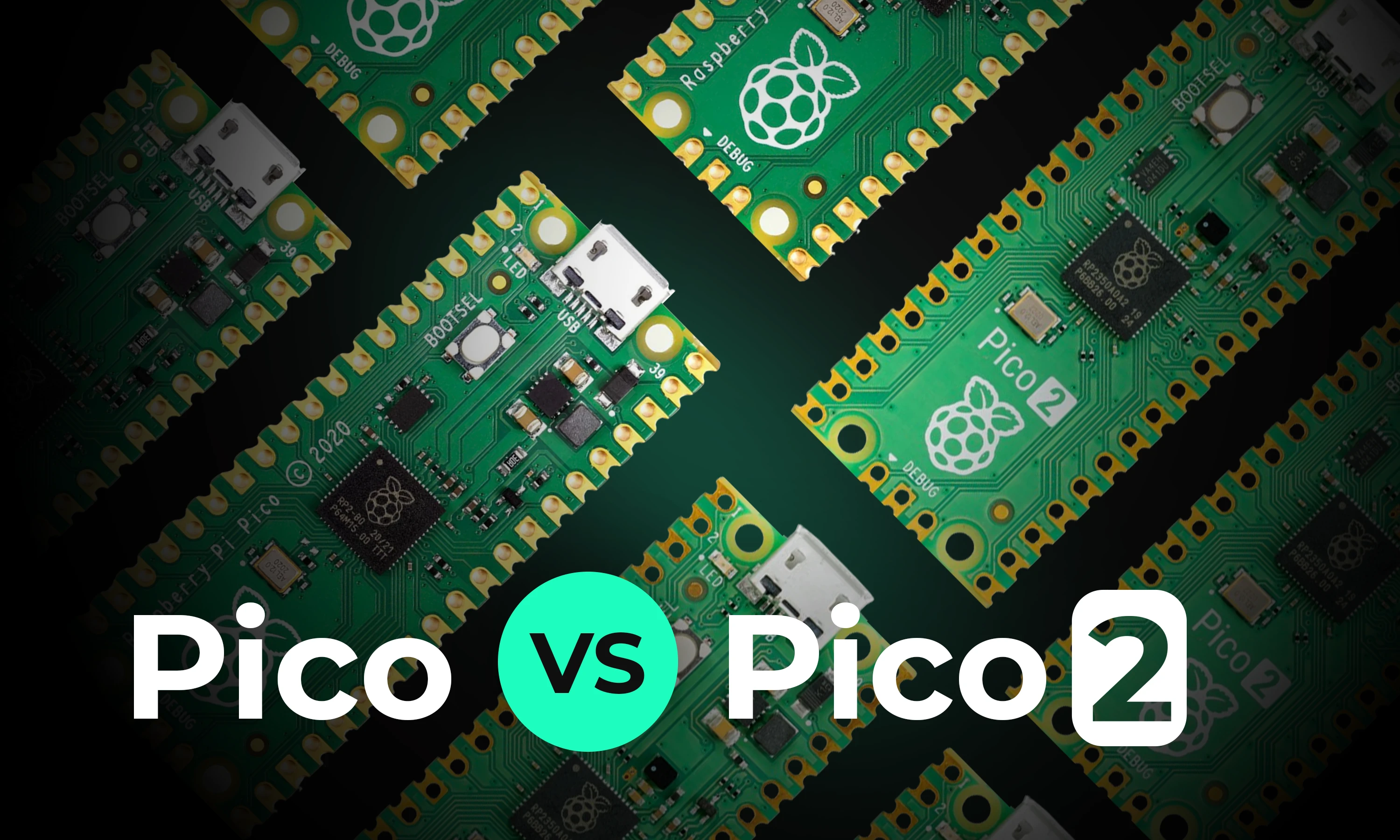
This article will explore the key differences between the original Raspberry Pi Pico and the new Raspberry Pi Pico 2, focusing on the most significant enhancements and what remains unchanged.

The Raspberry Pi Zero 2 W is a small and powerful computer with impressive performance for its size and price. With a quad-core processor, 512MB of RAM, built-in wireless connectivity, and a USB On-The-Go port, it's suitable for many projects, including home automation, media centers, and robotics.

This blog explores the powerful Arduino map() function, showing you how to scale values, control sensors, and master advanced programming techniques for innovative projects.
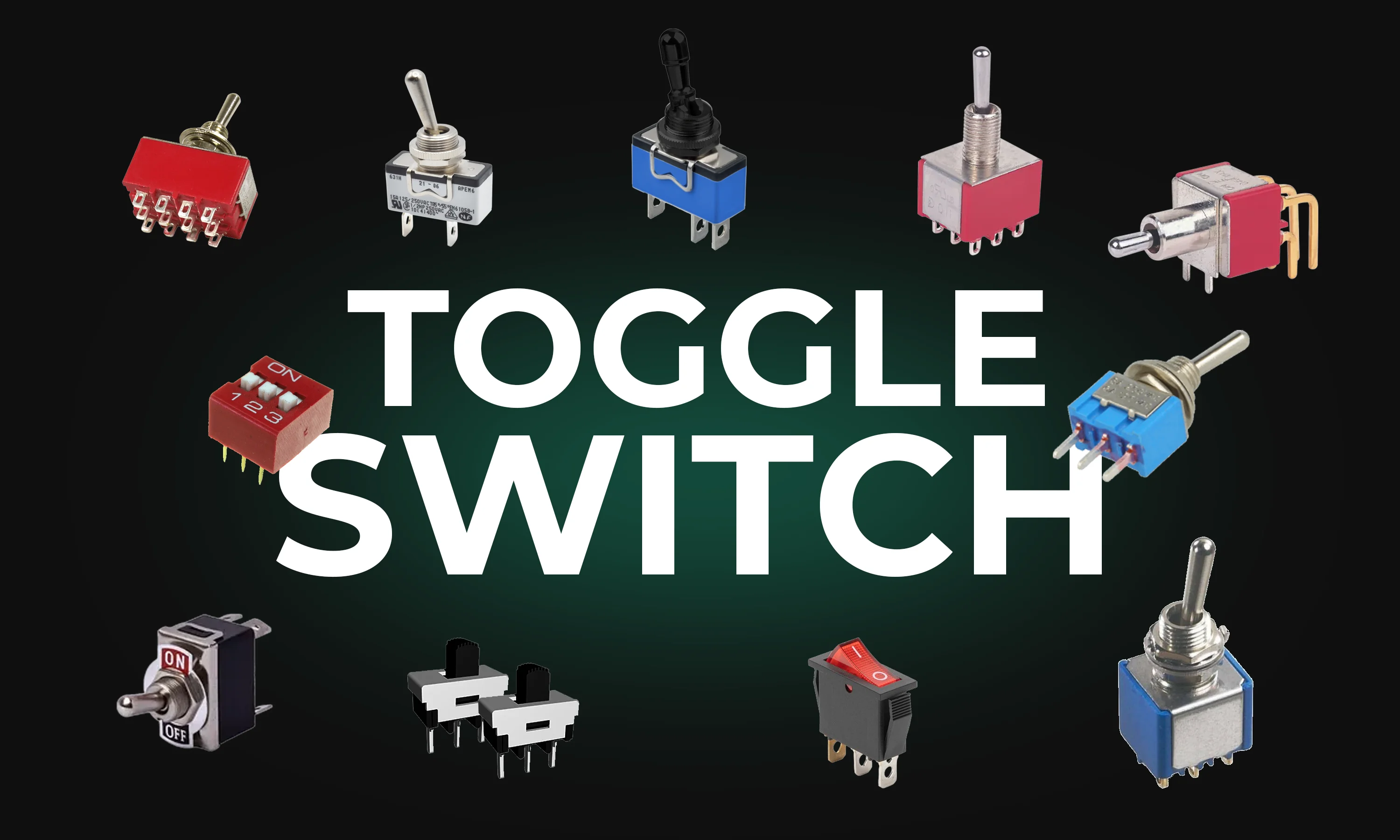
This guide explores toggle switches, their types, and applications in electronics. Learn how they work and find the right one for your project.

RJ45 connectors enable fast data and power transmission in Ethernet networks. They're vital for reliable connectivity in homes, offices, and data centers.

Voltage regulators ensure stable power in electronics. This post covers types, uses, and selection tips—plus how AI tools like Flux.ai streamline design.