In this post, we’ll show you exactly how to unlock the power of Flux Copilot for yourself: from writing rock-solid triggers to scoping entries at the project, user, and system levels.
RJ45 connectors enable fast data and power transmission in Ethernet networks. They're vital for reliable connectivity in homes, offices, and data centers.
With Flux.ai's AI Auto-Layout and Flux Copilot, hardware engineers can auto-route RJ45 footprints and verify pin assignments without installing any software.
RJ45 stands for "Registered Jack 45" and refers to the standard 8-position, 8-connector (8P8C) modular plug used in Ethernet networks. Though technically a misnomer (the true RJ45 was a telephone connector), the name has stuck throughout the networking industry.
These connectors evolved from telephone jacks to become the standard interface for Ethernet connections. You'll find them everywhere - connecting computers to routers, linking switches in server rooms, and terminating wall outlets in offices and homes.
RJ45 connectors follow two main wiring standards: T568A and T568B. Both use the same number and color of wires, but they differ in the positions of the green and orange wire pairs.
According to Schneider Electric, commercial and residential wiring in the US typically follows the TIA 568B color code. They emphasize that proper wire mapping is essential because incorrect pinouts can cause signal degradation and network failures. The ANSI/TIA-568.2-D standard provides detailed color-coding guidelines to ensure reliable network performance.
Ethernet cables with RJ45 connectors come in different categories with varying performance levels:
Higher category Ethernet cables generally offer better performance, including faster data transfer speeds and improved shielding against interference. However, they tend to be less flexible and come at a higher cost. For example, Cat5e cables support speeds up to 1 Gbps, Cat6 can handle up to 10 Gbps over shorter distances, Cat6a extends 10 Gbps speeds over longer distances with better shielding, and Cat7 and Cat8 provide even higher speeds and enhanced shielding for specialized applications.
Unshielded Twisted Pair (UTP) connectors:
Shielded Twisted Pair (STP) connectors:
Modular Jacks are standard RJ45 connectors with an 8P8C design for terminating Ethernet cables.
Keystone Jacks feature a snap-in design for easy insertion into wall plates and patch panels. They're more versatile and can accommodate various connector types.
Pass-Through RJ45 connectors allow wires to pass completely through before crimping, making it easier to verify proper wire alignment. These are particularly helpful for beginners.
RJ45 connectors form the backbone of structured cabling systems across three key layers:
This hierarchical approach enables scalable, maintainable networks. With Flux.ai's collaborative browser-based tools, multiple engineers can simultaneously review complex rack-and-stack RJ45 layouts, ensuring proper connectivity across all layers without coordination headaches.
Beyond data transmission, RJ45 connectors can deliver power through Power over Ethernet (PoE) technology:
PoE++ utilizes all four wire pairs in an Ethernet cable, unlike earlier standards that use only two pairs. It is backward compatible with 802.3af and 802.3at standards, allowing seamless integration with existing devices. This technology enables powering IP cameras, wireless access points, and other network devices without the need for separate power cables. Key benefits include simplified installation, reduced cabling costs, and enhanced power delivery for high-demand devices.
For reliable RJ45 connections, you'll need:
Basic installation steps:
Always test your connections with a network cable tester to verify proper wiring, check for shorts or opens, and confirm continuity. Refer to footprint guidelines in our documentation, and use Flux Copilot to auto-verify RJ45 schematic pinouts.
Common problems include:
For diagnosis, inspect connectors for visible damage, test with different cables, use cable testers, and check for corrosion or debris.
Solutions typically involve re-terminating cables with new connectors, ensuring firm connections, replacing damaged cables, or cleaning connectors.
RJ45 connectors may be small, but they're critical to network reliability. Understanding their specifications and proper implementation helps you build robust networks that minimize downtime. When designing hardware with RJ45 interfaces, Flux.ai's AI Auto-Layout, Flux Copilot, and browser-based collaborative environment eliminate installation headaches and streamline the PCB design process. Join our Slack community for hardware-design tips and start your free project today.

Voltage regulators ensure stable power in electronics. This post covers types, uses, and selection tips—plus how AI tools like Flux.ai streamline design.
A voltage regulator is your circuit's guardian, maintaining a constant output voltage despite input fluctuations or load changes. This stability is essential because most electronic components operate within specific voltage ranges. Too much voltage can damage components or reduce their lifespan. Too little can cause malfunctions or complete failure. As Wikipedia explains, a voltage regulator is "a system designed to automatically maintain a constant voltage."
Let's explore how these devices work, the different types available, and how to select the right one for your application. Next, we'll dive into operation principles, regulator types, key applications, selection criteria, and troubleshooting tips.
At its core, a voltage regulator works through a feedback control mechanism. The system constantly compares the output voltage to a fixed reference voltage. When it detects a difference, it adjusts to bring the output back to the desired level.
The main components include:
When input voltage rises, the regulator reduces conductivity through the pass element. When input voltage drops, it increases conductivity. This dynamic response maintains stable output even during significant input fluctuations.
Linear regulators work like a variable resistor, continuously adjusting to maintain the desired output voltage. They're the simplest type of regulator and operate by dissipating excess voltage as heat.
Advantages:
Drawbacks:
Common examples include the 78xx series (like the 7805 for 5V output) and Low-Dropout (LDO) regulators that can operate with minimal voltage difference between input and output.
Switching regulators use a different approach. They rapidly switch a pass element on and off, storing energy in inductors or capacitors during the "on" phase and releasing it during the "off" phase.
These come in three main topologies:
Switching regulators achieve much higher efficiency (often 85-95%) than linear regulators. This makes them ideal for battery-powered devices and high-power applications. But they generate more noise and require more components.
AI-driven layout tools, such as Flux AI's Auto-Layout, offer advanced capabilities to significantly enhance the design process by optimizing trace flows. These tools utilize artificial intelligence algorithms to analyze and arrange circuit layouts in a way that minimizes electromagnetic interference (EMI). By intelligently routing traces, AI-driven layout solutions help reduce noise and signal degradation, leading to improved overall performance and reliability of electronic devices.
Shunt regulators divert excess current away from the load to maintain a stable voltage. The TL431 programmable precision shunt regulator provides a 2.5 V reference and allows adjustable output via two resistors—ideal for precision reference and over-voltage protection.
Digital or programmable regulators allow output voltage adjustment through digital interfaces. These modern regulators often include additional features like telemetry feedback and fault reporting.
Voltage regulators are everywhere in modern electronics:
When selecting a voltage regulator, consider these factors:
Don't forget to check our Documentation and join the Slack Community for design tips and peer support.
Voltage regulators are the unsung heroes of electronics—protecting components, ensuring steady performance, and extending lifespan. By mastering their principles, comparing types, and following best practices, you'll build rock-solid systems. And with Flux.ai's browser-based, no-install platform—featuring AI Auto-Layout (learn more), Flux Copilot for on-the-fly component recommendations, multi-MCU support, collaborative editing, and seamless documentation (docs)—you can design, verify, and iterate faster than ever. Ready to optimize your next power regulation circuit with AI assistance? Visit flux.ai today!
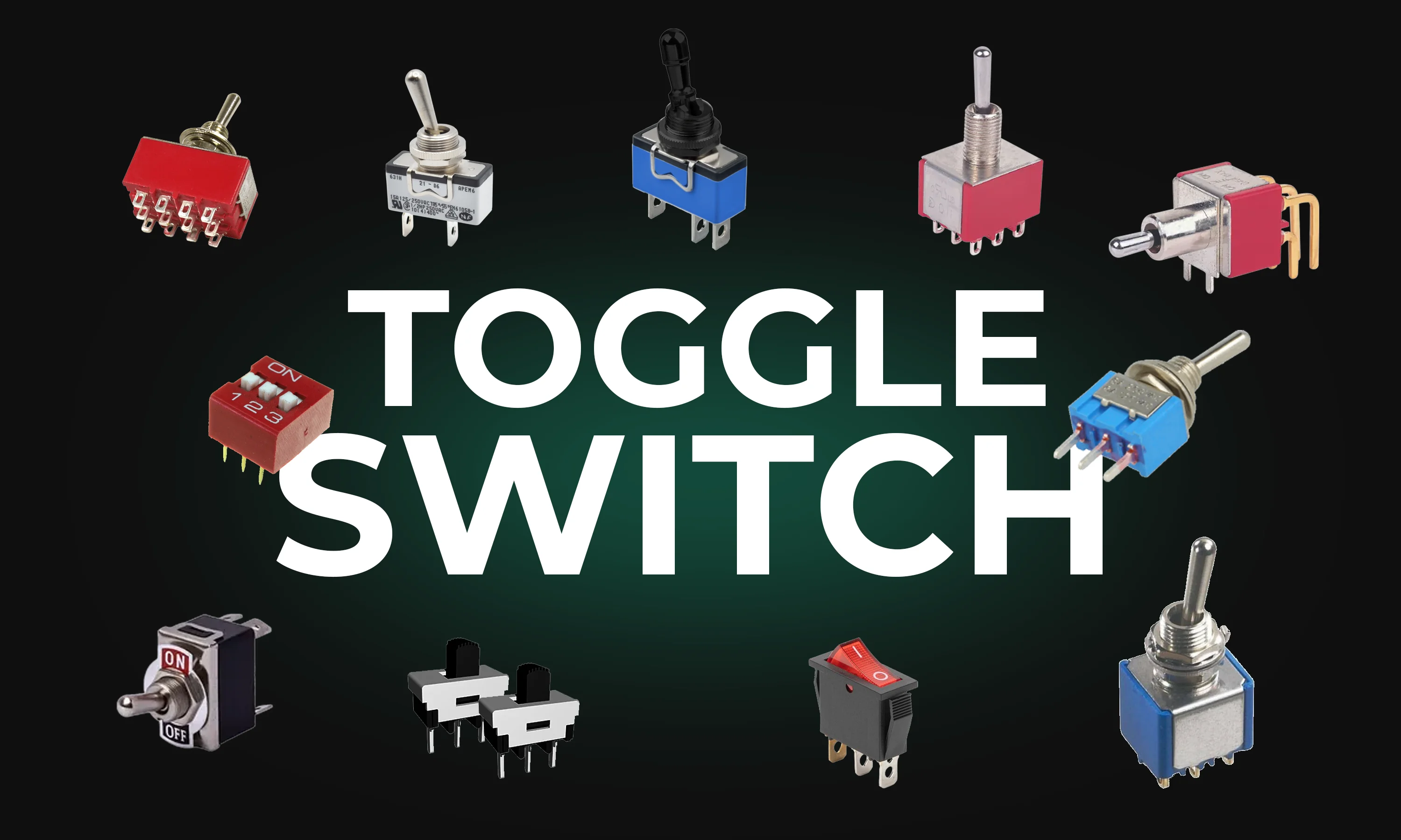
This guide explores toggle switches, their types, and applications in electronics. Learn how they work and find the right one for your project.
A toggle switch is a mechanical device that opens or closes an electrical circuit by moving a lever back and forth. It is named after its characteristic toggle action, which makes a definitive "on" or "off" position. Toggle switches come in various designs and configurations to suit different applications.
There are several types of toggle switches, each designed for specific functions and environments. Here are the most common types:
Toggle switches are used across various industries and applications, including:
The working mechanism of a toggle switch is straightforward:
Some advanced toggle switches also include LED indicators or built-in resistors for enhanced functionality.
When selecting a toggle switch for your project, consider the following factors:
Toggle switches are indispensable components in electrical and electronic systems. Their versatility, ease of use, and variety of configurations make them ideal for countless applications. By understanding the types, uses, and selection criteria, you can confidently choose the right toggle switch for your project, whether it's a simple DIY circuit or an industrial control system.
Understanding amps and volts is key to working with electronics. This guide explains their roles, relationship, and practical applications.
Amps, short for amperes, measure electrical current—the flow of electric charge through a conductor. Think of current as the rate at which electrons move in a circuit. More amps mean more electrons are flowing per second.
For example:
Volts measure electrical potential difference or "pressure" in a circuit. It’s the force that pushes electrons to move through a conductor. Higher voltage means greater potential to drive electrical current.
For example:
Amps and volts are interdependent and linked by Ohm's Law, which is fundamental in electronics:
Ohm’s Law: V = I * R
Where:
This means:
One of the best ways to visualize amps and volts is to compare electricity to water flowing through a pipe:
Higher water pressure (voltage) pushes more water (current) through the pipe, but if the pipe is narrow (high resistance), less water flows regardless of the pressure.
Here are some common scenarios where understanding amps and volts is helpful:
Understanding the difference between amps and volts is essential for anyone working with electronics or electrical systems. Amps measure the flow of current, while volts measure the force driving that flow. Together, they determine how electricity powers devices. By grasping their relationship and practical applications, you'll be better equipped to design circuits, troubleshoot issues, and choose the right components for your projects.
This blog explores the powerful Arduino map() function, showing you how to scale values, control sensors, and master advanced programming techniques for innovative projects.
The Arduino map() function is a versatile and widely used tool for scaling numbers from one range to another. Whether you're a beginner or an experienced Arduino enthusiast, understanding how this function works and how to use it effectively is crucial for optimizing your projects. In this blog, we’ll cover everything from what the map() function does to practical examples and advanced tips for its use.
map() Function?At its core, the map() function takes an input number within a specific range and maps it to an output number within a different range. This is especially useful when working with sensors, where raw data needs to be converted into meaningful values like temperature, distance, or percentage.
The syntax for the map() function is straightforward:
The function calculates the mapped value using this formula:
map() Function?In Arduino projects, raw sensor data often needs to be scaled for meaningful interaction. For example:
Using the map() function simplifies your code and reduces errors that can arise from manually calculating scaled values.
A common use case for the map() function is reading the input from a potentiometer and converting it to a different range. Here’s an example:
This code reads the raw analog value from a potentiometer and maps it to a percentage (0-100%). This is ideal for applications where you want to control brightness, volume, or other scaled parameters.
map() FunctionServo motors usually operate within a range of 0 to 180 degrees. If you're using a joystick with an analog output, you can map its range (0-1023) to match the servo's range:
The map() function can be used to adjust the brightness of an LED using PWM. Here’s an example:
map() FunctionHandle Out-of-Range Values: The map() function does not automatically constrain input values to the defined range. For safety, you can use the constrain() function:
Floating-Point Mapping: The map() function only works with integers. For floating-point precision, you can implement a custom version:
Inverse Mapping: You can reverse the input and output ranges to invert the mapping. For example, map 0-1023 to 255-0 for inverting brightness:
map()map() for Nonlinear Scaling: The map() function only provides linear scaling. For exponential or logarithmic scaling, you need custom formulas.The Arduino map() function is a simple yet powerful tool that enhances the flexibility and functionality of your projects. From controlling servos to scaling sensor data, its applications are vast and varied. By mastering its use and understanding its limitations, you’ll be well-equipped to handle a wide range of Arduino projects.
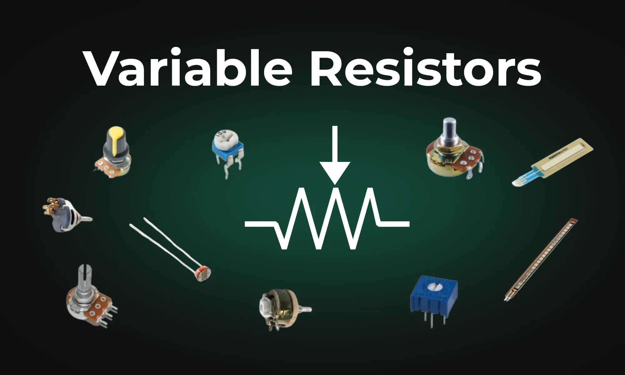
This article provides an overview of six types of variable resistors, including potentiometers, rheostats, photoresistors, wirewound resistors, thermistors, and varistors, highlighting their unique uses in electronic circuits. It also covers advanced applications and emerging technologies like digital potentiometers and memristors, emphasizing their significance in electronic control and adaptability.
Potentiometers, often referred to as "pots," enable fine control of resistance by using a dial or sliding element. The resistive element of a potentiometer can be adjusted using a wiper, controlled by turning a knob. Along with the “wiper” terminal, potentiometers have two additional terminals, typically referred to as “input” and “output” terminals. Two common types of potentiometers are linear and rotary. Linear potentiometers find use in applications like volume control on audio devices, while rotary potentiometers are employed in settings requiring rotational adjustment, such as tuning radio frequencies. They come in various forms, including carbon film and metal oxide variants.
Rheostats are specialized variable resistors designed with only two terminals. While potentiometers are used to control voltage, the primary use of rheostats is to control current in a circuit, adjusting electrical resistance as needed. The two terminals are connected in series with a load (e.g., a light bulb or motor). Adjusting the position of a wiper along the resistance wire changes the resistance in series with the load, thus controlling the current. Common applications of rheostats include dimmer switches for lights and motor speed control.
Photoresistors, also known as light-dependent resistors (LDRs), are two-terminal resistors that change in response to light levels. An LDR exhibits a decrease in resistance as light intensity increases, enabling it to sense and react to environmental light changes. This property makes an LDR ideal for applications like automatic lighting control and light-sensitive alarms.
Wirewound resistors, constructed by winding a resistive wire around an insulating core, are known for their precision and ability to handle high power levels. Although having both fixed and variable variations, variable wirewound resistors allow for the length of the resistance wire included in the circuit to change, altering the resistance. Wirewound resistors also have two terminals. Wirewound resistors are used in applications that demand precise resistance values, such as in precision instruments and high-power electronic circuits.
Wirewound resistors come in both precision and power varieties. Precision wirewound resistors offer high accuracy and low tolerance, making them suitable for applications like voltage dividers and precision amplifiers. Power wirewound resistors are built to withstand high power levels, ensuring they can maintain their resistor value under challenging conditions, making them suitable for high-current circuits and power amplifiers.
Thermistors are temperature-sensitive resistors with two terminals that exhibit changes in electrical resistance with temperature fluctuations. They are classified into two primary types: negative temperature coefficient (NTC) and positive temperature coefficient (PTC). NTC thermistors decrease resistance with increasing temperature, while PTC thermistors exhibit the opposite behavior, making them essential in temperature control systems, such as thermostats, and are vital for temperature compensation in various electronic circuits.
Varistors, also known as voltage-dependent resistors or VDRs, are specialized two-terminal variable resistors designed to protect electronic circuits from voltage spikes and surges. They exhibit a high electrical resistance under normal conditions but rapidly decrease their resistance when exposed to excessive voltage. This behavior allows varistors to shunt excessive voltage away from sensitive components by allowing high current to flow through the varistor instead. Varistors find use for surge protection in electronic systems.
To provide a quick reference, here's a table summarizing these six types of variable resistors:
Voltage dividers are circuits that divide an input voltage into smaller output voltages usually using resistors. Variable resistors, and especially potentiometers, are useful components in creating variable voltage divider circuits. By adjusting the resistance, you can finely control the output voltage.
Variable resistors are at the heart of electronic control and adaptability, and understanding their diverse types and applications is a vital step toward becoming proficient in electronics.