In this post, we’ll show you exactly how to unlock the power of Flux Copilot for yourself: from writing rock-solid triggers to scoping entries at the project, user, and system levels.
We’re incredibly excited to announce that we have decided to open up Flux and move out of private beta! What does this mean? If you’re a current user of Flux - nothing will change for you. For new users, this means that we’re now allowing anyone and their team to signup!
Hey everyone! We’re incredibly excited to announce that we have decided to open up Flux and move out of private beta! What does this mean? If you’re a current user of Flux - nothing will change for you. For new users, this means that we’re now allowing anyone and their team to signup! Exiting the private beta is a huge milestone for all of us and we have a lot to thank you and the community for. Over the course of the 2-year private beta, we’ve had 25,000 engineers join and over 240,000 projects created in Flux! We can’t thank you enough for taking a chance and joining a generational effort of reimagining how PCBs get made. It’s your candid feedback, ideas, and encouragement that enabled us to dare to change this and build Flux. And we are just getting started, so consider this our warm up lap 🚀!
In terms of pricing, nothing will change. Our mission is to take the hard out of hardware and enable anyone to design PCB boards and make electronics hardware. As such we are fully committed to always have a no nonsense free tier that allows you to host up to 10 private projects and unlimited public projects. If those 10 private projects are not enough, we offer a Pro tier at $12/mon per editor that features unlimited private projects. Now what about team tiers and features you ask…bring the upvotes!
When we started out 3 years ago, we knew that we were embarking on a monumental effort that would require early and ongoing input from hardware engineers. That’s why we decided to launch Flux embarrassingly early and build in public, learn in real time, and build a community that pushes back against the forces of stagnation in EDA/CAD tooling and is ready for change.
Wow! Did you deliver. ❤️ Everything we’ve built was inspired by insights we gained during the series of events we hosted, video calls, heated slack debates, and passionate email exchanges. And frankly the naysayers who told us that change is impossible; that it should be resisted; that it goes against human nature - change isn’t optional. It happens all the time. And we live to prove the naysayers wrong!
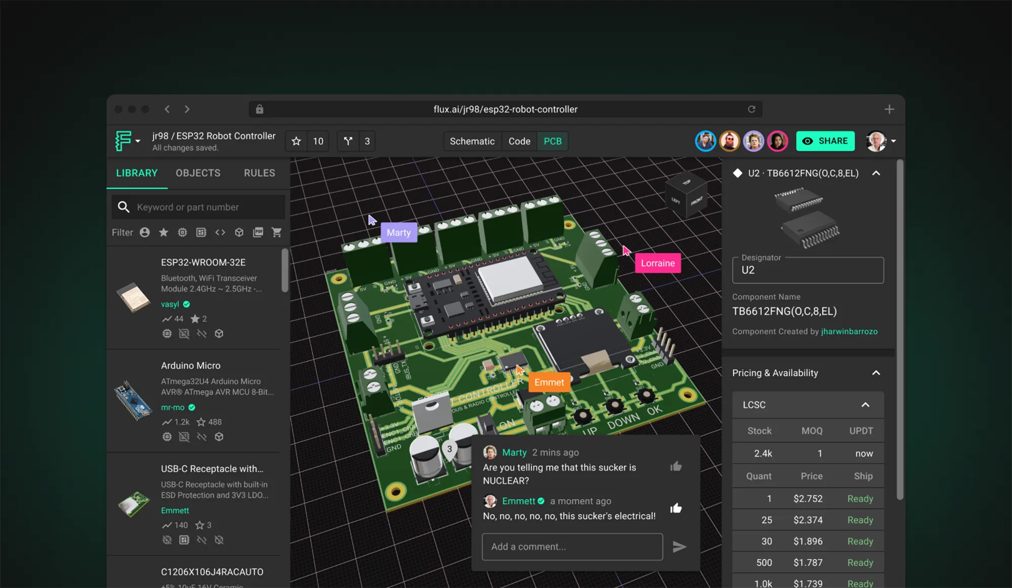
We knew that to make the big leaps in PCB design we wanted, we would need to build it from the ground up with re-usability, speed, and collaboration at the forefront. This took time, but we think it is worth it. Some of the major features that make Flux’s PCB editor different from others include:
In terms of performance improvements, we were able to make huge gains to enable projects of increasing complexity with less lag. Our goal is for Flux to provide better performance than native applications and be available on any device type, from high end CAD workstations to your phone or tablet.
It’s been incredibly inspiring to see what people have been building in Flux, and how fast they’ve been able to design projects. Kerry Chayka, who worked on the iPhone motherboard for 7 years, puts it well “As a one man hardware startup, Flux gives me the super powers I need to work as fast as an entire team. Customers come to me with rough ideas of what they want and I’m able to build a product mockup before our first meeting even happens. I can do something that usually takes 2 months in half a day”.
At Flux, we’re inspired by a no nonsense and plug-and-play philosophy that makes it 10x faster and easier for anyone to create, share, and remix projects with others. If you think about how easy it is today for a 12 year old to build an iPhone app, our dream is to make it as easy for them to build their own iPhone. That’s what drives us to host competitions such as the recent Custom Arduino Shield Competition to create awesome shields, HATs, and wings...to have more of the building blocks for your projects available. Here are some of our favorite submissions:
Our current competition is focused on Energy Harvesting if you’re interested in getting involved. We’re looking for projects that can capture any type of energy, such as solar, kinetic, thermal, or RF; and no, wall chargers don’t count.

Over the last 2 years, we’ve been incredibly fortunate to grow our team from 10 to 22 with former engineers from Apple, NASA, and Facebook from all over the world. I think what makes our team unique from other software companies is that we love and build hardware! From high intensity strobe lights to drum machines, we’re always using Flux to build our own projects, which makes it easier to figure out what needs to be improved.
Want to get involved? You can check out open full-time positions here. There’s also plenty of part-time opportunities and sponsorships available to those who are interested. Feel free to reach out to Nico on Slack if you want to figure out how to plug in.
This milestone is really just one step forward towards our mission to take the hard out of hardware. We still have a long way to go, and I hope that the collaboration with the community will only continue to grow.
Just because we’re exiting private beta doesn’t mean we have everything figured out! We’re constantly looking for ways to improve and your feedback is absolutely critical to making an EDA tool that everyone loves. You can always submit feature requests or report bugs and we’ll do our best to address them quickly. Here’s a handful of the improvements we’re focused on.
Interested in helping us take the hard out of hardware? Tell your friends! Let them know that we’re opening up public availability and encourage them to signup and get involved. Talk about us on your favorite forums and other online communities, or post about us on social media. Every little bit helps!
Thanks again for all the support during the private beta. We really appreciate all the candid feedback, your patience, and your encouragement as we push forward.
Onward 🚀
Matthias & Lance
The ATmega328p stands out in the microcontroller world; our post breaks down its datasheet and pinout, offering valuable insights into its functionality and versatility. Learn how this powerful microcontroller can enhance your projects.
At the core of many electronic projects lies the ATmega328p, an 8-bit microcontroller belonging to Atmel's AVR series running off of a Reduced Instruction Set Computer (RISC) architecture. RISC architecture is advantageous due to its simplicity, which results in faster execution, improved compiler optimization, and better support for parallelism.
The ATmega328p is equipped with 32KB of ISP (In-System Programmable) flash memory, 1KB of EEPROM (Electrically Erasable Programmable Read-Only Memory), and 2KB of SRAM (Static Random-Access Memory).
Embedded systems often require the ability to store data persistently. The ATmega328p addresses this need with its onboard EEPROM. This non-volatile storage space is crucial for storing data that needs to persist across power cycles.
Developers can utilize the EEPROM for storing configuration parameters, calibration data, or any other critical information that requires retention.
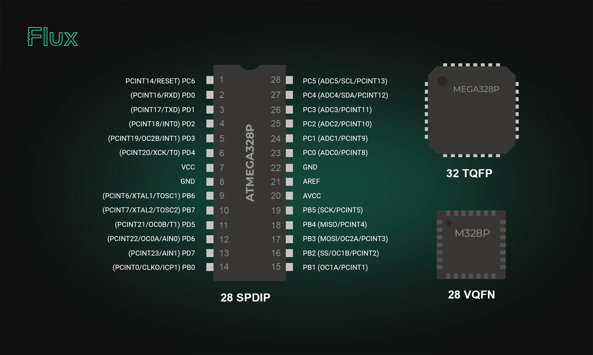
With 32 pins, the large number of digital and analog I/O pins is a key strength of the Atemga328p. The device boasts 23 general-purpose I/O (GPIO) lines, including analog inputs for sensor integrations. With a total of 6 analog input pins, developers can seamlessly interface with various sensors, converting real-world analog signals into digital data for processing.
There are two VCC pins (pin 4 and pin 6) and one AVCC pin (pin 18) for voltage supply, three GND pins (pin 3, pin 5, and pin 21) for grounding, and additional pins for 22pF capacitors, vital for stabilizing the 16MHz crystal oscillator.
The ATmega328p excels in managing inputs and outputs with three bi-directional GPIO ports, two 8-bit ports—PortB and PortD–and one 7-bit port–PortC. These ports serve as I/O interfaces, allowing users to control or read from external devices. Each I/O port pin may be configured as an output with symmetrical drive characteristics, or an input with or without pull-up resistors of 20 - 40 K ohms. Each bit in a Port corresponds to a specific pin, granting granular control over the connected peripherals. Understanding the DDR (Data Direction Register) is crucial for manipulating the ports. It determines whether each pin in a port operates as an input or output. For instance, setting a specific bit in DDRB to 1 configures the corresponding pin in PortB as an output.
Ensuring a stable 5V supply is vital for consistent performance, and the ATmega328p comes equipped with robust voltage regulation capabilities. The microcontroller operating voltage range is 1.8V to 5.5V, making it adaptable to various power supply configurations.
The ATmega328p offers several power-saving modes, allowing developers to tailor power consumption based on project requirements. These modes are particularly beneficial for energy-sensitive applications, extending battery life, or enabling solar-powered solutions.
Notable features of the ATmega328p include a plethora of options for serial communication (SPI, I2C, USART), two 8-bit Timer/Counters, one 16-bit Timer/Counter, and a 6-channel 10-bit A/D converter (ADC) enabling analog signal acquisition.
The atmega328p supports SPI, I2C, and USART, essential for communicating with other microcontrollers or modules.
A dedicated SPI interface enables high-speed, full-duplex communication. The following table outlines the key pins associated with SPI:
Integrating SPI-enabled devices, such as external flash memory or display modules, becomes seamless with the ATmega328p.
I2C support further extends the microcontroller's communication capabilities. The ATmega328p's I2C pins are:
This protocol is invaluable in projects requiring communication with multiple devices on the same bus.
USART enables serial communication and is crucial for interfacing with devices like GPS modules or Bluetooth modules. The USART pins on the ATmega328p are:
The ATmega328p provides flexibility in choosing between internal and external clock sources. This choice, such as opting for an external 16MHz crystal, significantly influences precision and power consumption.
Built-in timer counters enable the ATmega328p's time-sensitive capabilities. These timers provide accurate timing intervals and pulse-width modulation (PWM) functionality.
The ATmega328p’s 6-channel 10-bit Analog-to-Digital Converter (ADC) significantly enhances its capability to acquire and process analog signals. This ADC functionality is instrumental in translating real-world analog data, such as sensor inputs, into digital values that can be processed by the microcontroller.
This module is capable of translating analog voltages into a 10-bit number ranging from 0 to 1023, based on the inputted range of expected voltages (from 0 V to the voltage of the VCC). The microcontroller provides flexibility in choosing from six input sources, but only one channel can be converted at a time. The ADC module operates with a conversion speed of approximately 15,000 samples per second (15 ksps), ensuring swift and efficient signal processing.
The ATmega328 and ATmega328P are microcontrollers from the same family but have some differences:
The ATmega328P is not discontinued. While there was an indication on a distributor's website (Mouser) suggesting that the ATmega328P-MU variant is scheduled for obsolescence and will be discontinued by the manufacturer, this information should be interpreted with caution.
The Arduino Uno board, one of the most popular Arduino boards, uses the ATmega328p as its central processing unit. This integration has played a significant role in popularizing the ATmega328p, making it synonymous with user-friendly yet powerful microcontroller projects.
While Arduino offers easy access to the ATmega328’s capabilities, there are some applications that require utilizing the ATmega328p standalone, without the Arduino framework. Programming the ATmega328p standalone has a steeper learning curve, but provides a more granular and customized approach.
Focusing on Arduino Mega, Micro, and Uno, the blog details how the Mega 2560 stands out with its extensive memory and numerous I/O pins for sophisticated projects.

The Arduino Mega is a veritable powerhouse among Arduino boards. When raw computational muscle is what you need for your project, the Mega is the answer. It's powered by the ATmega2560 microcontroller, boasting a clock speed of 16MHz. This 8-bit microcontroller offers a substantial amount of flash memory, 256KB to be precise, which is a game-changer for projects requiring extensive code or data storage. Here are some key features of the Arduino Mega:
The Arduino Mega is a go-to choice for projects that demand an extensive range of digital and analog pins. Its generous 54 digital I/O pins and 16 analog input pins make it ideal for complex robotics, 3D printers, and other projects requiring multiple sensors and actuators. The 15 PWM pins provide precise control over motors and servos, which is a significant advantage for robotic applications. Additionally, the vast 256KB of flash memory ensures that even the most complex code can be accommodated.

The Arduino Uno is the quintessential Arduino board. It's the board that most beginners start with, and for good reason. It's straightforward, versatile, and perfect for learning the ropes of microcontrollers. The Arduino Uno is powered by the ATmega328P microcontroller, running at 16MHz, and offers the following features:
The Arduino Uno may not be as feature-rich as the Mega, but it has its own set of advantages. Its simplicity makes it an excellent choice for beginners, and its smaller size allows it to be easily integrated into various Arduino projects. With 32KB of flash memory, it can handle most small to medium-sized projects with ease. The 6 PWM pins provide ample control for motors and LEDs, and the 14 digital I/O pins are sufficient for many applications.

The Arduino Micro is the compact sibling in the Arduino family. It offers an excellent balance of performance and size, making it an ideal choice for portable and space-constrained projects. Here are some of its key specifications:
The Arduino Micro is an excellent choice when you need a microcontroller that can fit in tight spaces. It's also noteworthy for its 7 PWM pins, which provide fine-grained control over various components, and 20 digital I/O pins, giving you the flexibility to connect multiple sensors and actuators. With 32KB of flash memory, it can handle a wide range of projects while maintaining its compact form factor.
Some important specifications on these boards are flash memory and clockspeed, but what are they? Flash memory serves as the digital canvas where your code and data are stored. Think of it as your project's memory bank, and the larger the capacity, the more room you have to store complex code and information. On the other hand, clock speed determines the rate at which the microcontroller processes instructions. A higher clock speed signifies a faster computational engine.
In addition to the features discussed so far, it's important to mention two benefits of using any of these Arduino microcontrollers:
All three Arduino models support ICSP (In-Circuit Serial Programming), which allows you to reprogram the microcontroller without removing it from your project. This can be a handy feature, especially when you want to make updates or changes to your code without disassembling your project.
While the default operating voltage for these boards is 5V, it's worth noting that they can be adapted for 3V operation with some care. This is useful when working with components that require a lower voltage supply, such as many sensors and microSD cards.
The choice between the Arduino Mega, Arduino Uno, and Arduino Micro ultimately depends on the requirements of your project, so consider the following factors:
Regardless of your choice, with the right board in hand, your Arduino project will be ready to take flight!
Delve into the essentials of circuit diagrams, exploring the various electronics symbols and their roles in design, while also offering practical advice for effective use of diagramming tools like Flux.
Though people use the terms "circuit diagram" and "schematic diagram" interchangeably, subtle differences exist between them. A circuit diagram leans more toward representing the physical aspects of an electrical circuit, indicating the layout and wiring connections. In contrast, a schematic diagram focuses on the function and logic behind each component, utilizing electrical symbols and electronic symbols to depict how they connect.

The resistor is a fundamental component that restricts current flow. Its symbol in a circuit diagram and schematic diagram is a jagged line. Understanding resistor placement and ratings is essential for controlling voltage and current in your circuit.

Capacitors store and discharge electrical energy. They are symbolized by two parallel lines in schematics and circuit diagrams. Incorrectly placing a capacitor can lead to ineffective signal filtering or energy storage.

An inductor symbol resembles a coiled line and is integral in applications like energy storage and signal filtering. Understanding inductors in a circuit diagram is crucial for radio-frequency circuits and power management.

These semiconductor devices can either amplify signals or act as a switch. Transistors consist of three terminals: the base, collector, and emitter. Depending on the type of transistor, its symbol varies slightly but is easily recognizable.
Logic gates are the bread and butter of digital circuits. They perform basic Boolean operations like AND, OR, and NOT. Different shapes represent these gates, allowing for rapid identification and understanding of the circuit's digital logic.
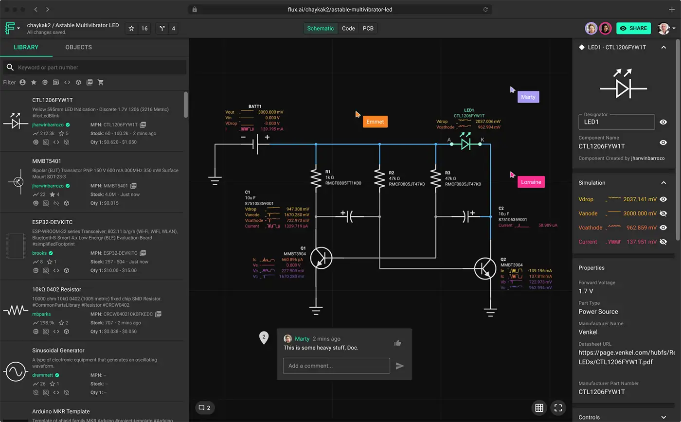
While hand-drawing circuit diagrams remains a valuable skill, software or web app like Flux or KiCad provides a more efficient, error-proof method for diagramming. These tools allow you to create intricate circuit and schematic diagrams, complete with every electrical symbol and electronic symbol you need. Moreover, these tools can generate a netlist, a text-based representation of the circuit that provides details about the connections between components, enabling seamless transitions from design to prototyping.
In both circuit and schematic diagrams, a netlist serves as a valuable asset. It is a textual depiction of the electrical circuit, listing every component and its connections. Engineers often generate netlists from software like KiCad, which then serves as input for simulations or as guidelines for physical circuit assembly.
A circuit diagram stands as a nexus between the theoretical framework and practical implementation of an electrical circuit. It is a tool for visual communication, using a well-defined set of electrical and electronic symbols to represent complex circuitry. Beyond merely a drawing, it serves as a functional map, especially when enhanced by software tools like KiCad and supplementary elements like netlists.
By grasping the basic components like resistors, capacitors, inductors, and transistors, along with more advanced elements like logic gates, engineers can navigate the complexities of electronic design. Thorough understanding enables one to transition from novice tinkerer to seasoned designer, proficient in creating both circuit diagrams and their more logic-focused counterparts, schematic diagrams.
Whether you're sketching your initial design or refining your final product, recognizing the nuances and best practices in diagramming can set you on the path to more effective, efficient, and innovative electronic creations.
Today, we’re thrilled to launch a powerful new feature that allows you to declare project requirements like operating temperature, voltage, or compliance standards so Copilot can leverage that knowledge to accelerate tedious tasks like BOM verification, debugging, and part recommendations freeing you to do more of the work you love.
Today, we’re thrilled to launch a powerful new feature that allows you to declare project requirements like operating temperature, voltage, or compliance standards so Copilot can leverage that knowledge to accelerate tedious tasks like BOM verification, debugging, and part recommendations freeing you to do more of the work you love.
Embarking on a new medical device project or crafting electronics designed to withstand the vacuum of space? Compliance standards are likely on your radar. To streamline this process we’re introducing Copilot Presets, a suite of community-driven templates tailored for various applications. You can simply choose from our favorites, fork, and modify them to fit your unique needs:
These presets are not a one-size-fits-all solution; they evolve with you. As your project requirements change, you can easily modify the properties, and Copilot will seamlessly update its understanding.
The best part? Copilot's memory ensures that whether you're revisiting a project or inviting collaborators to contribute, everyone stays on track with the latest requirements. It's a smarter, smoother, more cohesive experience that adapts to your workflow.
Imagine you’re designing an audio amplifier and you want to communicate your project requirements to Copilot. Simply add properties to your project like operating voltage, human interface, connectivity, and power requirements to give Copilot more context. Feel free to check out the full list of project requirements we used in this Audio Amplifier example.

One of the new key benefits of Copilot is its ability to remember and apply your project requirements throughout the entire design process.
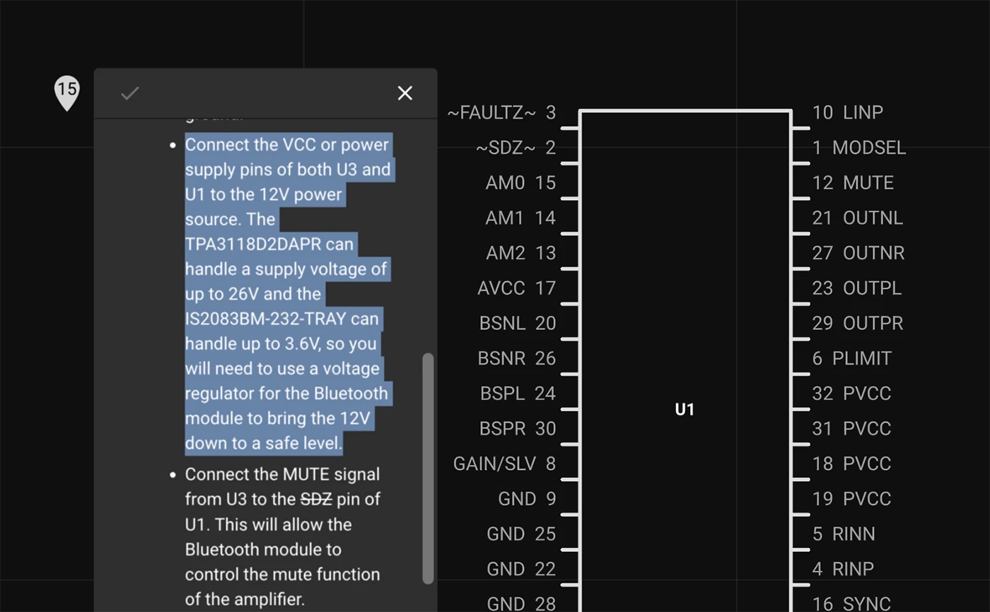
While working on the Audio Amplifier project, I asked Copilot to connect U3 to U1, assuming that was the correct move. With its understanding of our specific project requirements, Copilot quickly identified that I’d need a voltage regulator for the Bluetooth module. This correction brought the 12V down to a safe level, ensuring our design complied with the energy efficiency requirement.
This early error detection is more than a convenience: it's a safeguard against potentially costly and time-consuming mistakes. By integrating Copilot into your design process, you're not just leveraging an intelligent tool; you're collaborating with an attentive and informed co-designer.
By keeping tabs on crucial details, Copilot saves you time and minimizes risks so you can concentrate on the big picture.
Choosing the right components for a project is complicated and project requirements can often become a tangled web of specs, datasheets, and constraints.
Copilot untangles that complexity and tells you exactly what you need and why you need it, balancing the project’s variables and constraints. . When you ask for part recommendations, Copilot doesn’t just toss out generic suggestions. It evaluates every single project requirement as an engineer would—comprehensively and contextually.
When I queried,
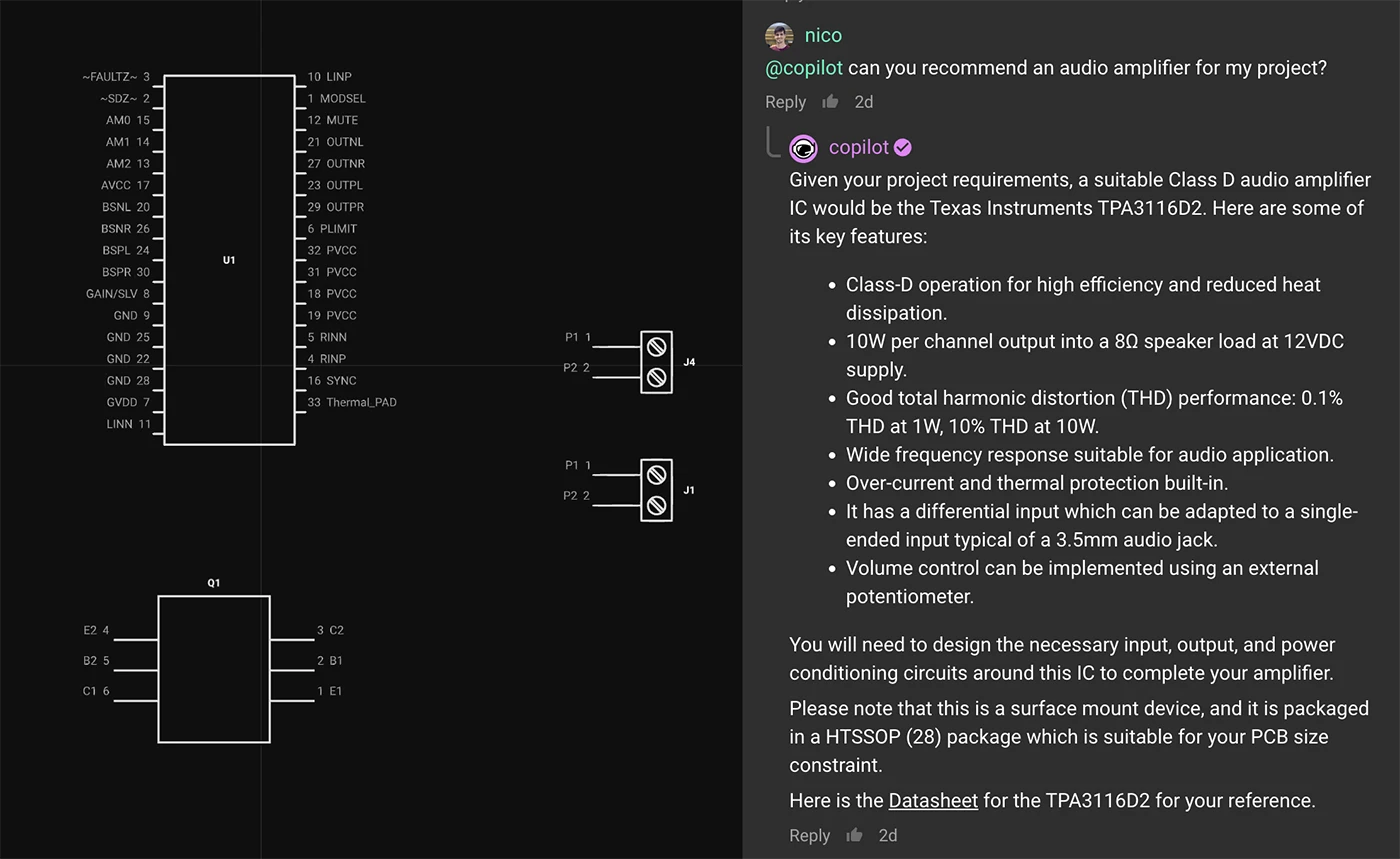
@copilot, can you recommend an audio amplifier for my project?
The response wasn't just a list of options. Copilot explained the reasoning behind the recommendation, aligning it with my project objectives. It recognized the need for energy efficiency, matching input sources, and the desired output power.
Checking all the parts in your BOM to ensure that they meet your project requirements takes forever. Now, Copilot can do it for you! You can ask questions like,
@copilot is my project RoHS compliant?
Copilot will parse all of your component’s datasheets and check them against RoHS compliance in seconds.

Standards are critical to building great hardware, but the work of ensuring compliance to those standards sucks. Copilot handles the tedious busywork so you can focus on the next creative problem.
But this is about more than making your work more efficient. This is about making your work more meaningful, unlocking whole new categories of creative problems for you to solve. The better Copilot gets to know your project, the better Copilot can serve you. By using it, you’re evolving an AI to help you achieve your specific goals, accelerating your project and amplifying its impact.
Hardware engineers don’t become hardware engineers to reference datasheets. They do it, we do it, to solve hard problems, to invent new things, to make hardware that makes a difference in people’s lives. So do the work that really matters, and let Copilot handle the rest.
A new era of personalized AI is emerging, and we want to give you the tools to customize Copilot for your needs. Feel free to share your feedback, experiences, and your favorite Copilot Presets in our Slack community.
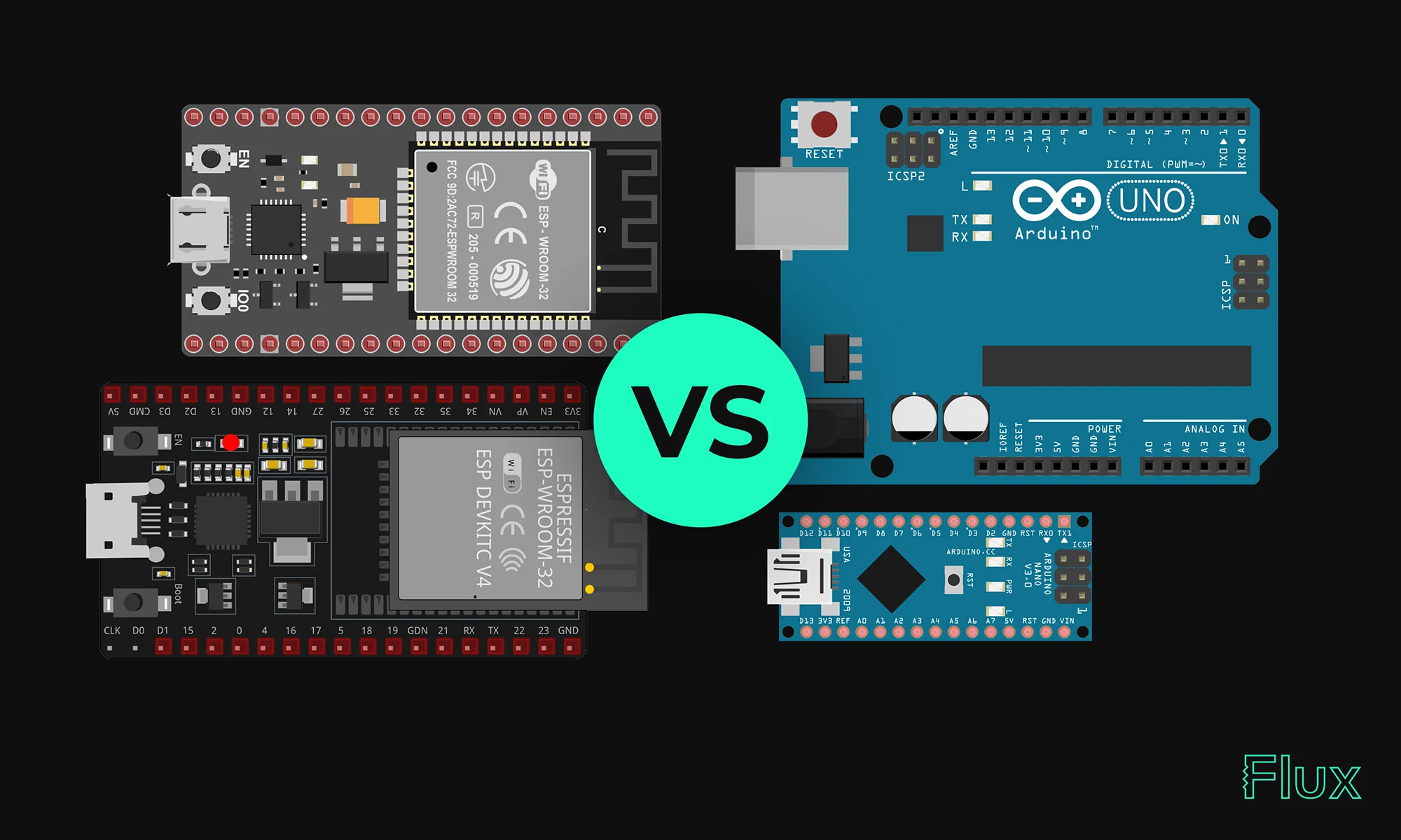
Our 2023 guide compares ESP32 and Arduino, two essential microcontrollers in IoT. ESP32 offers advanced features like Wi-Fi, while Arduino excels in ease of use and community support. Choose based on your project's complexity and needs.
Espressif has designed the ESP32 to come with a dual-core Xtensa LX6 microprocessor, 520KB of SRAM, and various interfaces for peripherals. It also supports Wi-Fi and Bluetooth, allowing seamless connectivity. ESP32 can be programmed using either the Arduino IDE or the ESP-IDF (Espressif IoT Development Framework), which is more complex and might be challenging for beginners. It is the successor of ESP8266 created by the same company, Espressif. ESP32 can be used in the form of a module or NodeMCU.
With higher clock speeds and the ability to perform parallel processing, ESP32 boasts impressive computational power. The availability of numerous GPIO pins and communication interfaces such as SPI, UART, and I2C provides flexibility in interfacing with different sensors and devices. In a way, ESP32 can be thought of as a devkit for connected devices.
If you want more details about the power consumption optimization, please refer to the ESP32 User manual found in Espressif website.
{{insert-project-1-here}}
Arduinos are based on a variety of microcontrollers, with the popular Arduino Uno using an ATmega328 microcontroller. The basic model includes 32KB of flash memory, 2KB of SRAM, and a modest 16MHz clock speed. The microcontrollers used in Arduino products include several GPIOs and common microcontroller communication interfaces like SPI, I2C, and UART.
Arduino boards typically offer lower processing power compared to ESP32 but are often sufficient for many applications. Similar to a devkit, the easy-to-use layout and a range of built-in components make them great for beginners.
When deciding between the ESP32 and Arduino, the answer largely depends on the specific needs and constraints of your project. Here are some factors to consider:
{{insert-project-2-here}}
{{insert-nico-video}}
ESP32's software ecosystem supports various programming languages like C, C++, and Python. The toolchain and SDK provided offer flexibility in development.
Programming the ESP32 may require a steeper learning curve compared to Arduino but offers greater control and efficiency, especially for complex applications.
To program the Arduino's microcontroller, the Arduino IDE is known for its simplicity, supporting C and C++. The wide variety of libraries and community support makes it approachable for newcomers. Arduinos are also compatible with microPython.
Coding in Arduino focuses on accessibility, with an extensive list of example codes and tutorials available. This has helped foster a large and supportive community around the platform.
ESP32 is suitable for advanced projects requiring higher processing capabilities and connectivity, like IoT devices, smart home applications, and industrial automation.
Arduino’s simplicity makes it a preferred choice for educational purposes, art installations, and hobbyist projects.
ESP32 offers advanced features and robust processing, making it suitable for complex applications. Arduino, with its user-friendly approach, is often the go-to for beginners and education. Below is a summary of their strengths and weaknesses.
{{insert-project-3-here}}
All things considered, the choice between ESP32 and Arduino largely depends on the project requirements. For complex, connected applications, ESP32 is the choice, while for simplicity and learning, Arduino is preferred. Understanding the nature of the project and weighing the strengths and weaknesses of each platform is key to making the right decision in 2023.
1. Can I use Arduino IDE to program ESP32?
Yes, ESP32 is compatible with the Arduino IDE, making it easier to program for those familiar with Arduino boards.
2. Which is better for IoT, ESP32 or Arduino?
ESP32 is generally better for IoT due to its built-in Wi-Fi and Bluetooth capabilities.
3. Is ESP32 more powerful than Arduino?
Yes, ESP32 has a dual-core processor, more RAM, and higher clock speeds, making it more powerful than most Arduino boards.